Support » Pololu USB AVR Programmer v2 User’s Guide »
3. Pinout and components
 |
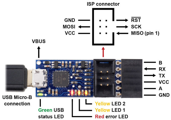
Pololu USB AVR Programmer v2.1, labeled top view. |
|---|
The Pololu USB AVR Programmer v2.x connects to a computer’s USB port via a USB A to Micro-B cable (not included).
The programmer has a standard 6-pin AVR ISP connector for programming AVRs. It connects to the target AVR device via an included 6-pin ISP cable. The cable has a keyed connector that matches the programmer’s shrouded header, making it impossible to plug the cable into the programmer in the wrong orientation. The older 10-pin ISP connections are not directly supported, but it is easy to create or purchase a 6-pin-to-10-pin ISP adapter. The six pins on the ISP connector are:
- MISO: The “Master Input, Slave Output” line for SPI communication with the target AVR. This is called PDO in some AVR datasheets. The programmer is the master, so this line is an input.
- VCC: By default, this line is an input that the programmer uses to measure the voltage of the target AVR (see Section 7). This line can also be configured to power the target device (see Section 8).
- SCK: The clock line for SPI communication with the target AVR. The programmer is the master, so this line is an output during programming.
- MOSI: The “Master Output, Slave Input” line for SPI communication with the target AVR. This is called PDI in some AVR datasheets. The programmer is the master, so this line is an output during programming.
- RST: The target AVR’s reset line. This line is used as an output driven low during programming to hold the AVR in reset.
- GND: Ground. This line should be connected to the target device’s ground.
When the programmer is not actively programming an AVR, the MISO, SCK, and MOSI pins are all high-impedance inputs.
The end of the programmer has a 6-pin serial header with a pinout that is similar to commonly-available FTDI cables and breakout boards. The programmer comes with a 6-pin right-angle female header soldered in. The six pins on this header are:
- GND: Ground. This is connected to the GND pin on the ISP header and the GND pin of the USB cable.
- A: By default, this line is just an input that is pulled up, but it can be configured to do serial control/handshaking functions (see Section 6.1).
- VCC: This is connected to the VCC pin on the ISP connector. By default it is an input, but it can be configured as an output for powering other devices (see Section 7 and Section 8).
- TX: This is a TTL serial output pin that can send data to another device (see Section 6.1).
- RX: This is a TTL serial input pin that can receive data from another device (see Section 6.1).
- B: By default, this line is configured to be the DTR (Data Terminal Ready) signal. It can be configured for other serial/handshaking functions (see Section 6.1) or it can be used as a clock output signal (see Section 5.10).
 |
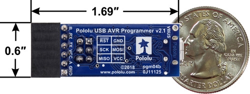
Pololu USB AVR Programmer v2.1, bottom view with dimensions. |
|---|
The programmer’s circuit board is 0.6″ wide and 1.35″ long. With the right-angle female header, it is about 1.69″ long.
The programmer has 4 LEDs that indicate its status. The behavior of these LEDs is described in detail in Section 4.4.
The VBUS line is connected directly to the USB cable’s 5V power supply line. It can be used to power external devices as long as you are careful not to draw too much current from it (see Section 8).
Included accessories
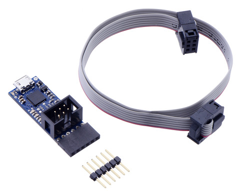
The Pololu USB AVR Programmer v2.x comes with the accessories shown in the picture below. The 6-pin ISP cable can be used to program AVRs. The 1×6 double-sided male header can be plugged into the serial header to effectively reverse its gender (making it possible to connect that header to a breadboard or female jumper wires). A USB A to Micro-B cable is required and not included.
 |
Pololu USB AVR Programmer v2 or v2.1 with included hardware. |
|---|


