Support » Pololu USB AVR Programmer v2 User’s Guide » 4. Getting started »
4.4. LED feedback
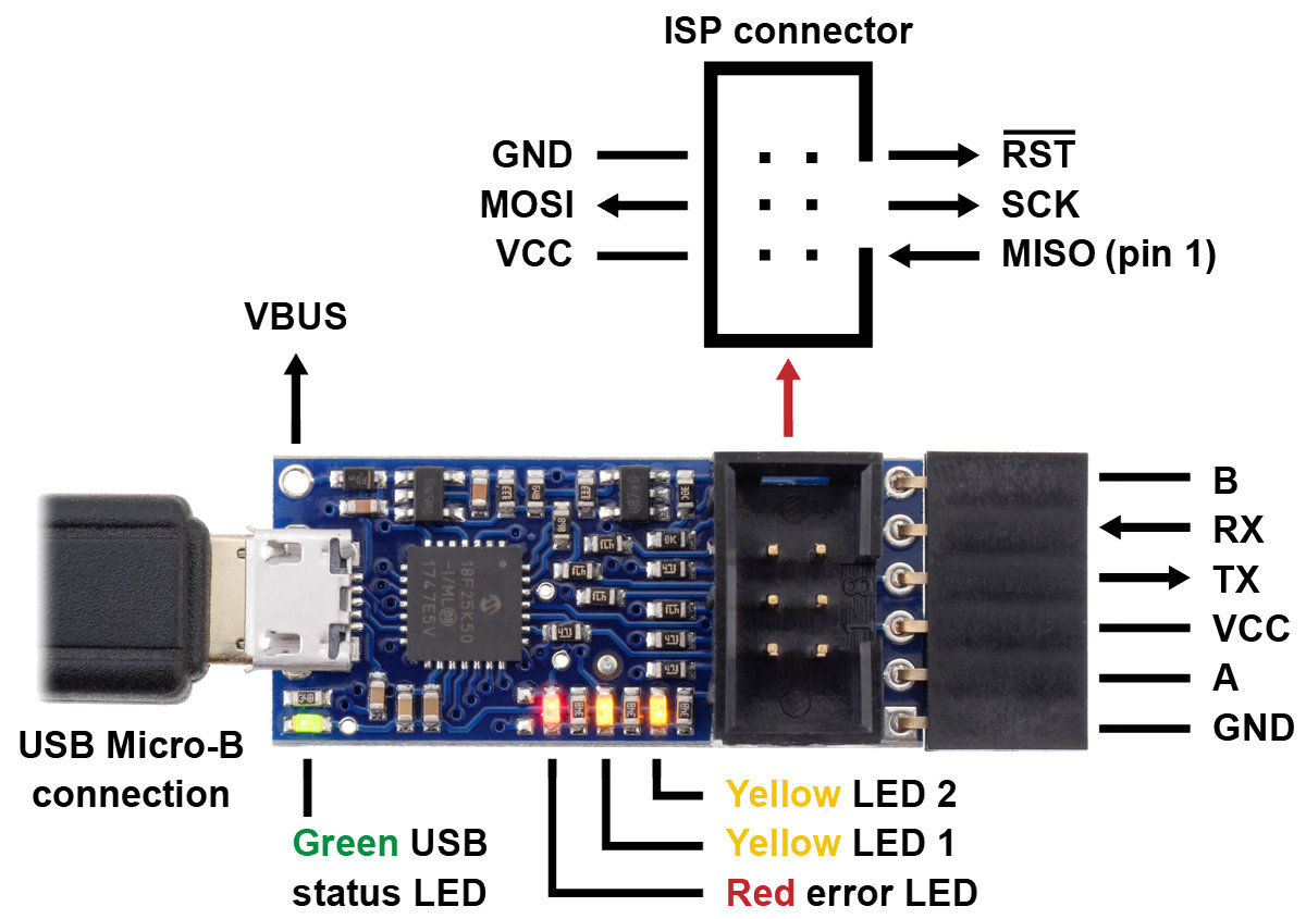 |
Pololu USB AVR Programmer v2.1, labeled top view. |
|---|
The Pololu USB AVR Programmer v2.x has four LEDs to indicate its status.
Most of the information provided by the LEDs is also available in the programmer’s configuration software. To see the programmer’s current status, just start the Pololu USB AVR Programmer v2 Configuration Utility or run pavr2cmd -s from a command prompt. However, learning the LED behavior can be helpful if you want to quickly make sure that the programmer is in the right state before using it.
The green LED indicates the USB status of the device. When you connect the programmer to the computer via the USB cable, the green LED will start blinking slowly. The blinking continues until the programmer gets a particular message from the computer that indicates that the programmer is recognized. After the programmer gets that message, the green LED will be on, but it will flicker briefly when there is USB activity. During suspend mode (e.g. while the computer is sleeping or while USB is disconnected and the programmer is inadvertently powered through its VCC pin), the green LED will be off but blink briefly every second to indicate that the programmer is powered but sleeping.
The red LED indicates an error or warning. When it is blinking, it means that the target AVR’s VCC power line is outside of the acceptable range. The red LED will blink about once per second, and the blinks will last about one half second (512 ms). When the red LED is on solid, it means that the last attempt at programming resulted in an error. You can determine the source of the error by running the programmer’s configuration software. If the target’s VCC line goes out of the acceptable range, the red LED will go back to blinking and no longer display the previous error even if target power is restored.
The two yellow LEDs indicate information about the programmer’s regulator mode, the current operating voltage of the programmer, and whether VCC is an output or not. More information about these settings can be found in the Power monitoring and regulator settings section and the Using VCC or VBUS to supply power section.
If VCC is configured to be an input (which is the default setting), the yellow LEDs behave as described below:
- If the programmer’s regulator mode is Auto (which is the default and means that it will automatically switch between 3.3 V and 5 V), and no power is currently detected on the target’s VCC line, then both yellow LEDs will be off. This is the default state of the programmer if you just plug it into a computer without changing any settings or connecting anything else. The red LED will be blinking because the target power is not detected.
- If the programmer’s regulator mode is 3.3 V (meaning that it always operates at 3.3 V), but the power on the the target’s VCC line is not within the acceptable range, then yellow LED 1 will blink once per second. Yellow LED 1 turns on a little bit (128 ms) after the red LED turns on, and turns off at the same time as the red LED. This blinking pattern is also used if the programmer’s regulator mode is Auto, and the programmer is currently operating at 3.3 V, but the voltage on the target’s VCC line is above the acceptable range.
- If the programmer is currently operating at 3.3 V and the target’s VCC level is within the acceptable range, then yellow LED 1 will blink briefly (64 ms) once per second.
- If the programmer’s regulator mode is 5 V (meaning that it always operates at 5 V), but the power on the target’s VCC line is not within the acceptable range, then both yellow LEDs will blink once per second. Yellow LED 1 turns on a little bit (128 ms) after the red LED turns on. Yellow LED 2 turns on a little bit (128 ms) after yellow LED 1. Both yellow LEDs turn off at the same time as the red LED. This blinking pattern is also used if the programmer’s regulator mode is Auto, and the programmer is currently operating at 5 V, but the voltage on the target’s VCC line is not within the acceptable range.
- If the programmer is currently operating at 5 V and the target’s VCC level is within the acceptable range, then both yellow LEDs will blink briefly (64 ms) once per second. Yellow LED 2 will blink a little bit after yellow LED 1 blinks.
If VCC is configured to be a 3.3 V output, then yellow LED 1 will blink eight times per second to warn you. If VCC is configured to be a 5 V output, then both yellow LEDs will blink eight times per second to warn you. If you want VCC to be an output but you do not want to see the yellow LEDs blinking so fast, you can change the “VCC Output Indicator” setting from “Blinking” to “Steady” using the configuration software. This makes the yellow LEDs just stay on solid instead of blinking eight times per second.
Note that the LED blinking patterns described above are not directly affected by measurements of the programmer’s actual operating voltage (VDD). In the descriptions above, a phrase like “operating at 3.3 V” just means that the programmer is trying to operate at that voltage.
To ensure that the programmer shows a complete blinking pattern instead of switching quickly between two or more patterns, the yellow LED blinking pattern is only updated once per second. So if you make a change to your system, you might have to wait for up to one second to see the LEDs respond.
The LEDs will be noticeably brighter when the programmer is operating at 5 V as opposed to 3.3 V.
Startup blinking
When the programmer starts running, it tries to detect if it was reset by some special condition. You can see the cause of the last reset in the configuration software’s “Last device reset” field, so it is usually easiest to just look there to diagnose any problem you are having with the programmer getting reset. The programmer also provides LED feedback to indicate why it was reset. If the programmer was reset by anything other than a standard power-on reset (which happens whenever power is turned on), the programmer will blink the red LED and/or yellow LED 1 in a special way for a second before it starts operating. The way these LEDs blink depend on the cause of the reset:
- If a brown-out reset occurred, the red LED will blink four times while the yellow LEDs stay off. A brownout-reset can happen if VCC is configured as an output and you are trying to power a device that has too much capacitance or draws to much current, as described in Section 8.
- If the programmer was reset by the reset line on its microcontroller, yellow LED 1 will blink four times while the red LED stays off. This should almost never happen.
- If the programmer was reset by its watchdog timer, then the red LED and yellow LED 1 will blink together four times. This is the expected behavior if the programmer was in bootloader mode and then received the USB command to quit the bootloader and start running the firmware.
- If any other type of non-standard reset happens, then the red LED will be on solid while yellow LED 1 blinks four times.
Bootloader mode
In bootloader mode, which is used for updating the firmware of the programmer itself and should only rarely be needed, the LEDs behave differently. The green LED still indicates the USB status, but it is different: after the programmer gets a particular message from the computer that indicates that the programmer is recognized, the green LED will start doing a double blinking pattern every 1.4 seconds. The yellow LED will usually be on solid, but it will blink quickly whenever a USB command is received. The red LED will be on if and only if there is no firmware currently loaded on the device.
Related products


Home | Forum | Blog | Support | Ordering Information | Lists | Distributors | BIG Order Form | About | Contact
© 2001–2026 Pololu Corporation
