Support » Pololu Simple Motor Controller User’s Guide » 5. Configuring Your Motor Controller »
5.1. Input Settings
The Input Settings tab of the Pololu Simple Motor Control Center allows you to quickly specify how you want to control the speed of the motor, and also allows you to set up limit and kill switches.
As a first step, we recommend that you click “Quick Input Setup…”. This will launch the Quick Input Setup Wizard, which will let you specify how you want to control of the motor, and (if you are using analog or RC) lets you quickly calibrate your inputs. When you finish the Quick Input Setup Wizard, your new settings will get saved in the Input Settings tab and will (optionally) be applied to the device so you can start using your new settings right away. After you are done running the Quick Input Setup, you should be able to successfully control your motor, as long as you have made all the necessary electrical connections as described in Section 4.
The rest of this section documents all of the Input Settings in detail. If you are able to control the motor the way you want to after running the Quick Input Setup Wizard, then you probably don’t need to read this section.
The serial settings in the Input Settings tab are not documented here. If you want to use the serial interface, please see Section 6.
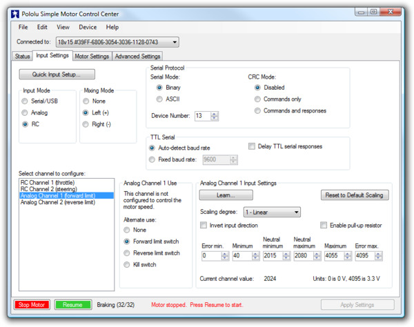 |
Input Settings tab in the Pololu Simple Motor Control Center. |
|---|
Input Mode
The Input Mode specifies what kind of input the controller will use to calculate the Target Speed of the motor. The available options are:
- Serial/USB: In this input mode, the Target Speed is specified by serial or USB commands, and the Target Speed is reset to zero whenever there is an error. This is the default input mode.
- Analog: In this input mode, the Target Speed is determined by the voltages measured on the analog signal lines (A1 and optionally A2 if you want to use mixing).
- RC: In this input mode, the Target Speed is determined by the pulse widths measured on the RC signal lines (RC1 and optionally RC2 if you want to use mixing).
Regardless of which input mode you choose, the Analog and RC input channels will always be measured; those channels can be used as limit or kill switches if they are not controlling the speed of the motor and their values can be retrieved using the Get Variable serial command.
Mixing Mode
If you have chosen Analog or RC as the Input Mode, the Mixing Mode setting specifies whether to use mixing and what type of mixing it is.
The primary use of mixing is for controlling a motor on a differential drive robot. You can use one Simple Motor Controller for each motor on the robot, and feed the same inputs in to both of them. We recommend connecting the throttle (forward/reverse) input to channel 1, and the steering (left/right) input to channel 2.
- None: In this mixing mode, the Target Speed is calculated as a function of the Scaled Value of the first channel only (Analog Channel 1 or RC Channel 1).
- Left (+): In this mixing mode, the Target Speed is calculated as a function of the sum of the Scaled Value of both channels.
- Right (-): In this mixing mode, the Target Speed is calculated as a function of the difference of the Scaled Value of both channels (channel 1 minus channel 2).
Note that in RC and Analog mode, the Target Speed depends not only on the Scaled Values of the channels, but also on the Starting Speed and Max Speed parameters, as explained in Section 5.2.
The table below summarizes all the input and mixing modes you can choose:
| Input Mode | Mixing Mode | Motor speed is calculated from… | Example Applications |
|---|---|---|---|
| Serial/USB | N/A | Serial and/or USB commands | Motor controlled by microcontroller or PC. |
| Analog | None | Analog Channel 1 | Motor controlled by joystick. |
| Analog | Left (+) | Analog Channel 1 plus Analog Channel 2 | Differential drive vehicle controlled by joystick. |
| Analog | Right (-) | Analog Channel 1 minus Analog Channel 2 | Differential drive vehicle controlled by joystick. |
| RC | None | RC Channel 1 | Electronic Speed Controller (ESC). |
| RC | Left (+) | RC Channel 1 plus RC Channel 2 | Differential drive RC vehicle. |
| RC | Right (-) | RC Channel 1 minus RC Channel 2 | Differential drive RC vehicle. |
The settings on the bottom half of the Input Settings tab are all channel-specific settings. To view or edit them, you must first select the desired channel using the list box in the bottom left corner.
Alternate Use
The Alternate Use setting allows you to configure any channel that is not used to control the speed of the motor as a limit or kill switch. The available options are:
- None: This channel will not be used for anything special, but its Raw and Scaled values can be read using serial or USB.
- Forward limit switch: When the scaled value of the channel is above 1600 (50%), the limit switch will be considered active and the motor will not be allowed to move forward. If the target speed is positive, a “Limit/kill switch” error will occur.
- Reverse limit switch: When the scaled value of the channel is above 1600 (50%), the limit switch will be considered active and the motor will not be allowed to move in reverse. If the target speed is negative, a “Limit/kill switch” error will occur.
- Kill switch: When the scaled value of the channel is above 1600 (50%), the kill switch will be considered active and the “Limit/kill switch” error will occur, preventing the motor from moving. For example, you could use the kill switch feature and the Serial/USB input mode to make an autonomous robot that you can conveniently immobilize from a distance using an RC transmitter and receiver.
The Forward and Reverse Limit Switch options allow you to set up limits that prevent your actuator from moving out of its allowed range. See Section 4.3 and Section 4.4 for information about connecting limit switches. You will probably want to avoid setting a motor deceleration limit if you are using a limit switch, because the deceleration limit will prevent the motor from stopping immediately: when the switch is triggered, the motor will gradually decelerate from its current speed to zero, which might be bad for your system depending on how it is set up.
Any channel configured as a limit or kill switch is considered a required channel. This means that the motor will stop if that channel becomes disconnected (the Required channel invalid error will occur).
Learn button
The Learn… button launches the Channel Setup Wizard, which lets you quickly calibrate your input channel or limit switch. Before using this wizard, you should select your desired Alternate Use and if you are configuring an analog channel then you should first enable the pull-up resistor and check “Ignore Pot Disconnect” in the Advanced Settings tab if necessary.
Enable pull-up resistor (analog channels only)
When checked, the Enable pull-up resistor option enables a pull-up resistor on the selected analog input line. The value of the resistor is approximately 40 kΩ and it pulls the line up to 3.3 V.
Scaling Parameters
The rest of channel-specific settings are all scaling parameters, which means they specify how the Scaled Value of the input channel is calculated from its Raw Value. They also specify the normal range of the input channel. All of these parameters except Scaling degree can be easily set using the Learn… button.
The Raw Value of a channel is measured directly from the input pin. For RC channels, the Raw Value is the width of received pulses in units of 1/4 μs; typical RC receivers will generate signals between 4000 (1000 μs) and 8000 (2000 μs). For Analog channels, the Raw Value is a 12-bit measurement of the voltage on the input line: 0 is 0 V and 4095 is 3.3 V. You can see the raw value of the selected channel by looking at the “Current channel value” label or by looking at the Status tab.
If the Raw Value is less than Error min or greater than Error max, then the channel is considered invalid and the Scaled Value is not computed. Otherwise, the Scaled Value of a channel is calculated from the Raw Value using the scaling parameters. Specifically:
- Raw values between Error min. and Minimum map to a Scaled Value of -3200 (or 3200 if “Invert input direction” is checked).
- Raw values between Minimum and Neutral minimum map to a Scaled Value between -3200 (or 3200 if “Invert input direction” is checked) and 0.
- Raw values between Neutral minimum and Neutral maximum map to a Scaled Value of 0.
- Raw values between Neutral maximum and Maximum map to a Scaled Value between 0 and 3200 (or -3200 if “Invert input direction” is checked).
- Raw values between Maximum and Error max. map to a Scaled Value of 3200 (or -3200 if “Invert input direction” is checked).
By default, the scaling is linear, but you can change the Scaling degree to use a higher-degree polynomial function, which gives you better control for low speeds.
The Error min. and Error max. parameters should be set so that the input channel’s Raw Value is always within that range whenever the input is operating properly. One way to do this is to move your input to the minimum position, and set Error min. to be 10–200 counts lower than the current channel value. Similarly, move your input to its maximum position, and set Error max. to be 10–200 counts higher than the current channel value.
The Minimum and Maximum parameters should be as far apart as possible to maximize the accuracy of your speed control, but they should still be close enough that you can reliably reach scaled values of ±3200 (±100 %). One way to do this is to move your input to its minimum position, and set Minimum to be 10–200 counts higher than the current channel value. Similarly, move your input to its maximum position, and set Maximum to be 10–200 counts lower than the current channel value.
The Neutral minimum and Neutral maximum parameters should be as close as possible to maximize the accuracy of your speed control, but they should still be far enough from eachother so that you can reliably reach a scaled value of 0 when you put your input in the neutral position (e.g. release your finger from the joystick). Some joysticks can settle at different positions depending on where you release the from, so you should experiment with releasing your joystick from different positions and see what Raw Values you get (you can see them using “Current channel value” label or in the Status tab). Then set Neutral minimum and Neutral maximum so that their range includes all of the values you saw, and has a reasonable margin. This guarantees that you will not waste any power driving your motor when your stick is in the neutral position.
If you want to restrict the scaled value of the channel to always be negative or always be positive, you can set the Minimum equal Neutral Minimum or you can set Maximum equal to Neutral Maximum. This could be useful for one-directional control of a motor but typical applications will not need this.
Related products


Home | Forum | Blog | Support | Ordering Information | Lists | Distributors | BIG Order Form | About | Contact
© 2001–2025 Pololu Corporation
