Support » Pololu Motoron Motor Controller User’s Guide » 3.2. Connecting everything »
3.2.1. Connecting a micro Motoron with an I²C interface
This section explains how to connect motor power, motors, and a microcontroller to the Motoron M1T550, M2T550, M1T256, M2T256, and M3T453, micro-sized controllers with an I²C interface.
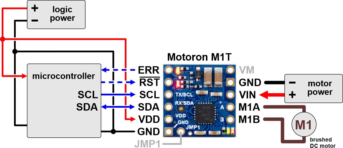 |
Typical wiring diagram for connecting a microcontroller to a Motoron M1T256/M1T550 Single I²C Motor Controller. |
|---|
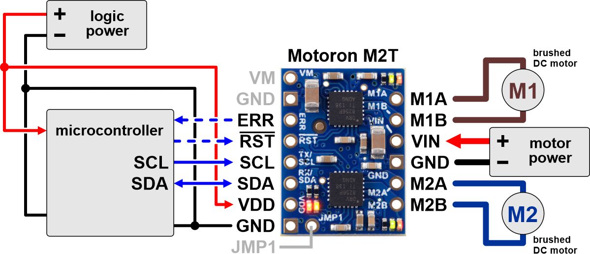 |
Typical wiring diagram for connecting a microcontroller to a Motoron M2T256/M2T550 Dual I²C Motor Controller. |
|---|
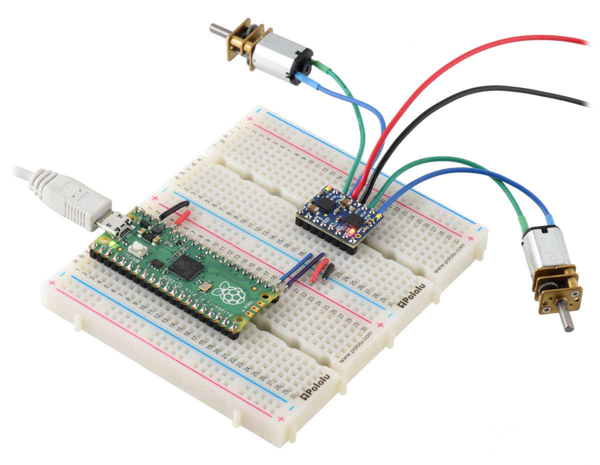 |
A Raspberry Pi Pico on a breadboard using a Motoron M2T256/M2U256 Dual Motor Controller to control two motors. |
|---|
 |
Typical wiring diagram for connecting a microcontroller to a Motoron M3T453 Triple I²C Motor Controller with JST SH-Style Connectors. |
|---|
 |
Typical wiring diagram for connecting a microcontroller to a Motoron M3T453 Triple I²C Motor Controller with 0.1″-Pitch Through-Holes. |
|---|
Making connections to 0.1"-pitch through-holes
You can buy a version of the Motoron that comes with male header pins already soldered, or you can buy a version with header pins included and do the soldering yourself. After your Motoron has header pins securely soldered to it, you can push the Motoron into a breadboard or connect its pins to jumper wires. Alternatively, you can make connections by directly soldering wires to the board. Regardless of which of these methods you choose, soldering is necessary to make reliable connections.
Making connections to JST SH-style connectors
If your Motoron version has a 4-pin JST SH-style connector, it is compatible with 4-pin JST SH-style cables. This 4-pin connector provides GND, VDD, SDA, and SCL. It is compatible with Sparkfun’s Qwiic and Adafruit’s STEMMA QT and also works with the Pololu Isolated USB-to-I²C Adapter with Isolated Power. If your Motoron has two 4-pin JST SH-style connectors, both connectors provide access to the same nodes you can use them interchangeably. If you are controlling multiple Motorons, you can chain them together using JST cables in order to connect them all to the same I²C bus.
| Pin | Typical wire color | Name | Function |
|---|---|---|---|
| 1 | Black | GND | Ground |
| 2 | Red | VDD | Logic voltage |
| 3 | Blue | SDA | I²C data |
| 4 | Yellow | SCL | I²C clock |
If your Motoron has a 2-pin JST SH-style connector, it is compatible with 2-pin JST SH-style cables. This 2-pin connector provides the power outputs for a single motor. It is compatible with JST SH-Style Connector Boards for Micro Metal Gearmotors.
| Pin | Typical wire color | Name | Function |
|---|---|---|---|
| 1 | Black | M1B, M2B, M3B | Motor output |
| 2 | Red | M1A, M2A, M3A | Motor output |
Connecting motor power and motors
The negative terminal of the motor power supply should be connected to the GND pin on the Motoron that is adjacent to VIN. The positive terminal of the motor power supply should be connected to the VIN pin. Note that connecting power to VIN does not power the Motoron’s microcontroller and does not cause any LEDs to turn on.
Each motor should have one lead connected to an MxA pin (M1A, M2A, or M3A) and the other lead connected to the MxB pin with the matching motor number. The Motoron’s concept of “forward” corresponds to MxA driving high while MxB drives low, so you might consider this when deciding which motor lead connects to which Motoron pin. You can also flip the wires later if you want to flip the direction of motion (assuming one side of the connection does not use a keyed connector).
Connecting a controller or adapter
You will need a controller with an I²C interface to send commands to the Motoron. The Motoron’s GND, SCL, and SDA pins should be connected to the corresponding pins of the controller board, and the Motoron’s logic voltage (VDD) should be connected to the logic voltage supply of the controller board (the allowable logic voltage range can be found in the specifications for your particular Motoron). The Motoron does not supply power to the controller board.
Alternatively, if you want to control the Motoron from a computer via USB, you can use an isolated USB-to-I²C adapter with isolated power which is capable of providing either 3.3 V or 5 V to power the Motoron’s logic voltage. Alternatively, you can use a isolated USB-to-I²C adapter that does not provide power and provide the logic power some other way. Either way, the Motoron’s GND, SCL, SDA, and VDD pins must be connected to the adapter.
Once you make the GND and logic power connections and turn on the logic power, you should see the Motoron’s yellow LED blink. The red LED will also turn on unless something is communicating with the Motoron and causing it to turn the LED off.
You can connect multiple Motorons to the same I²C bus. To control multiple Motorons on the same I²C bus independently, you will need to configure each Motoron to have a unique I²C address, as described in Section 3.5.
Related products


Related categories


Home | Forum | Blog | Support | Ordering Information | Lists | Distributors | BIG Order Form | About | Contact
© 2001–2026 Pololu Corporation
