Support » Pololu Dual TB9051FTG Motor Driver Shield User’s Guide » 4. Using as a general-purpose motor driver »
4.a. Assembly for use as a general-purpose motor driver
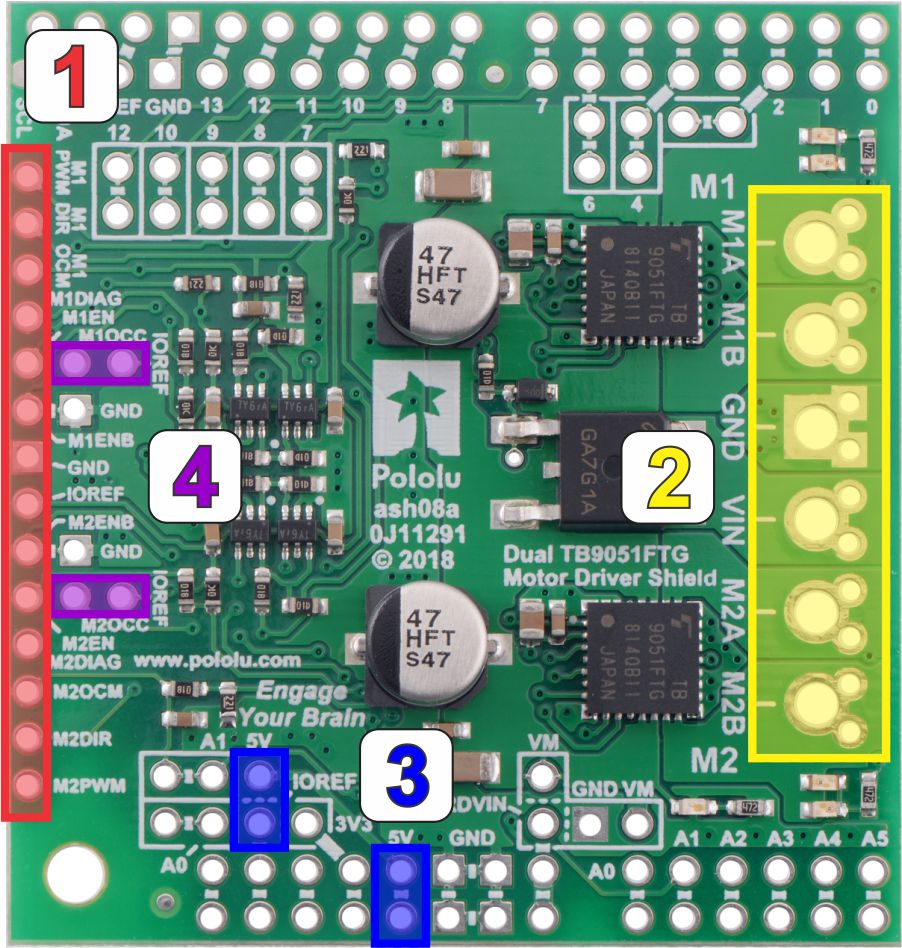 |
- Logic connections: The 14 small holes along the left side of the board, highlighted in red in the above diagram, are used to interface with the motor drivers. You can optionally solder a 1×14 piece of the included 0.1″ male header strip to these pins. Soldering the pins so they protrude down allows the logic side of the motor driver to be plugged into a standard solderless breadboard or perfboard. You can also solder 0.1″ female headers or custom connectors to these pins.
- Motor and power connections: The six large holes/twelve small holes on the right side of the board, highlighted in yellow in the above diagram, are the motor outputs and power inputs. You can optionally solder the included 5mm-pitch terminal blocks to the board to enable temporary motor and motor power connections, or you can break off an 1×12 section of the included 0.1″ header strip and solder it into the smaller through-holes that border the six large motor and motor power pads. Note, however, that each header pin pair is only rated for a combined 6 A, so for higher-power applications, the terminal blocks should be used or thick wires with high-current connectors should be soldered directly to the board.
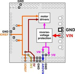
Dual TB9051FTG motor driver shield power buses.
- Logic power: The TB9051FTG drivers require 5 V but can accept logic signals from 3.3 V microcontrollers. Power needs to be applied to both the shield’s 5 V bus and the IOREF bus, which is used for the pullups on the board and should match your microcontroller’s power source (see the diagram to the right). There are several ways to do this.
- If your microcontroller uses 5 V, you can either:
- Connect 5 V to both the 5V pin highlighted in blue in the above diagram and the IOREF pin highlighted in red.
- Short together the pins labeled 5V and IOREF highlighted in blue (such as with a 1×2 male header strip and shorting block) and then connect 5 V to either of the two pins.
- If your microcontroller doesn’t use 5 V:
- Connect 5 V to the 5V pin and your microcontroller logic voltage to the IOREF pin.
- If your microcontroller uses 5 V, you can either:
- M1OCC and M2OCC to IOREF: The M1OCC and M2OCC pins set the drivers’ over-current response. By default, the drivers remain disabled after an over-current condition, but if the OCC pins are high, they automatically try to resume driving after a short delay instead. You can optionally solder a wire or a 1×2 piece of the included 0.1″ male header and install a shorting block to short the M1OCC and M2OCC pins to the IOREF voltage.

Related products


Home | Forum | Blog | Support | Ordering Information | Lists | Distributors | BIG Order Form | About | Contact
© 2001–2026 Pololu Corporation
