Support » Pololu A-Star 328PB User’s Guide » 4. Getting Started »
4.2. Connecting to the serial interface
The A-Star 328PB has a TTL serial interface that allows you to upload programs using the serial bootloader and to send and receive serial data. The serial interface consists of the following six pins:
- GND
- GND, usually connected to CTS on a serial adapter to drive it low
- VCCIN – alternative power input
- TX – TTL serial data output
- RX – TTL serial data input
- D/R – DTR/RTS, used by the serial adapter to trigger a reset
This serial interface is compatible with our USB AVR Programmer v2.1 and commonly available USB-to-serial adapter cables (e.g. FTDI cables). We recommend using the Pololu USB AVR Programmer v2.1 because it can be configured to operate at either 3.3 V or 5 V, and it can program the A* over the ISP interface as well as the serial interface.
The TX and RX lines are directly connected to the ATmega328PB microcontroller, without any level shifting. To avoid issues due to mismatched voltages, it is best to use a USB-to-serial adapter that operates at the same voltage as the A-Star 328PB board you want to program. The Pololu USB AVR Programmer v2.1 can be configured to operate at either 3.3 V or 5 V, so it is suitable for both 3.3 V and 5 V A-Stars.
The VCCIN pin is an alternative power input that you can use to power the A-Star 328PB. Many USB-to-serial adapter cables provide power on this pin, and the Pololu USB AVR Programmer v2.1 can be configured to optionally provide either 3.3 V or 5 V power on this pin. The A* board includes a switching circuit that makes it safe to have both VCCIN and BAT+ power supplies connected at the same time. If power is supplied to VCCIN, It is important for the voltage to match the regulator voltage on your board, as detailed under the “Power” heading in Section 3.
The D/R pin is used to reset the ATmega328PB. It should be connected to the DTR or RTS control signal from the serial adapter, and a falling edge (which occurs when the control signal is asserted) will cause the A-Star’s microcontroller to reset. This feature, called “auto reset”, is often used by Arduino-compatible boards to automatically reset the microcontroller into bootloader mode before a program is serially uploaded to it. If your A-Star is running at 5 V while your serial adapter is running at 3.3 V, the auto reset feature will not work, so we recommend using a serial adapter that operates at the same voltage as the A-Star.
To connect a USB AVR Programmer v2.1 to the A-Star 328PB’s serial interface so that you can upload programs or send and receive serial data, follow these instructions:
- Open the Pololu USB AVR Programmer v2 Configuration Utility software. Set the “Regulator mode” to match the operating voltage of your A-Star. Make sure that the “Line A function” and “Line B functions” settings are set to their default values, which are “(none)” and “DTR” respectively.
- Record the name of the “TTL port” shown in the software. You will need this later when configuring the Arduino IDE or other software to talk to the A-Star.
- Connect the programmer’s 6-pin serial interface to the A-Star 328PB’s 6-pin serial interface. If you have soldered male header pins into the A-Star, you can simply plug it into the programmer’s 6-pin female header, with D/R connecting to the programmer’s B pin.
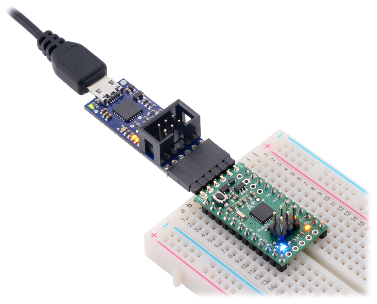 |
A-Star 328PB Micro connected to the serial pins of a Pololu USB AVR Programmer v2.1. |
|---|


Home | Forum | Blog | Support | Ordering Information | Lists | Distributors | BIG Order Form | About | Contact
© 2001–2026 Pololu Corporation
