Support » Jrk G2 Motor Controller User’s Guide » 7. Details »
7.4. Analog/frequency feedback handling
This section documents the details of how the Jrk G2 reads its analog and frequency feedback inputs in order to set the “Feedback” variable, and how it scales those inputs in order to set the “Scaled feedback” variable.
Analog feedback on FBA
When the Jrk’s “Feedback mode” is set to “Analog voltage” or the “Always configure FBA for analog input” option is enabled, the Jrk uses the FBA pin as an analog input. Once per PID period, the Jrk takes a configurable number of readings of the FBA pin. The “Analog samples” option in the “Feedback” tab controls how many readings to take. The Jrk has a 10-bit analog-to-digital converter (ADC), so each reading is a number between 0 and 1023. These readings are added together and bit-shifted appropriately to get a number between 0 and 65,472 which is stored in the “Analog reading FBA” variable, which can be read from the Jrk over USB, serial, or I²C.
If the “Feedback mode” is set to “Analog voltage” then the Jrk will set its “Feedback” variable to be equal to the “Analog reading FBA” variable divided by 16. A feedback value of 0 roughly corresponds to a voltage of 0 V, while a feedback value of 4092 roughly corresponds to the voltage on the Jrk’s 5V pin.
The “Detect disconnect with power pin (AUX)” option, which is only available when the “Feedback mode” is set to “Analog voltage”, causes the Jrk to drive the AUX pin low once per PID period after measuring FBA. If the voltage on the FBA pin does not drop by at least a factor of two while AUX is low, then the Jrk reports a “Feedback disconnect” error (if that error is enabled). The AUX pin drives high at other times.
The “Wraparound” option, which is only available when the “Feedback mode” is set to “Analog voltage”, specifies that the Jrk should consider a scaled feedback value of 4095 to be adjacent to a scaled feedback value of 0 when calculating the “Error” in the PID algorithm. This is useful for systems where the motor can rotate continuously over a full circle, and you want the system to take the shortest path between any two points on the circle.
The FBA pin does not have a pull-up resistor.
Frequency feedback on FBT
The Jrk measures the frequency of digital pulses on the FBT pin. The voltage on FBT should be between 0 V and 5 V with respect to GND. FBT is read as a digital input, and the signal must be below 1 V to be guaranteed to read as low and above 4 V to be guaranteed to be read as high. The FBT pin is pulled up to 5 V by an on-board 100kΩ resistor. There are two frequency measurement methods: pulse counting and pulse timing.
In pulse counting mode, the Jrk will count the number of rising edges on the FBT pin each PID period (which is 10 ms by default). At the end of each PID period, it will set the “FBT reading” variable to the number of rising edges that occurred during that PID period, assuming that the “Pulse samples” setting has its default value of 1. If the “Pulse samples” setting is more than 1, the Jrk will set the FBT reading to the number of rising edges from the last several PID periods, where the number of PID periods is specified by the “Pulse samples” setting. The FBT reading will then be divided by the value of the “Frequency divider” setting to obtain a frequency measurement that can be used to set the “Feedback” variable as described below.
In pulse timing mode, the Jrk will measure the width (duration) of pulses on the FBT pin. The “Pulse timing polarity” option controls whether it measures high pulses (“Active high”) or low pulses (“Active low”). The pulse width is measured as a number between 0 and 65535, in units of pulse timing clock ticks (one divided by the pulse timing clock frequency). The pulse timing clock can be set to wide range of frequencies from 1.5 MHz to 48 MHz. The “Pulse samples” setting specifies how many pulse widths to average together. The “Pulse timing timeout” setting specifies how long to wait before the Jrk starts recording pulses of maximum width (65535 ticks). (This is what allows the frequency measurement to decrease to its lowest possible value when the motor stops.) The Jrk sets the “FBT reading” variable to the average pulse width. A frequency measurement is obtained by computing 0x4000000 (2 raised to the power of 26) divided by the pulse width, and the frequency measurement is divided by the value of the “Frequency divider” setting before it is used to set the “Feedback” variable as described below.
After the Jrk has obtained a frequency measurement using either the pulse counting or pulse timing method, if the “Feedback mode” is “Frequency”, the Jrk will set the “Feedback” variable to 2048 plus or minus the frequency measurement, restricted to be between 0 and 4095. It will use “plus” if the “Target” variable (which specifies the desired speed) is 2048 or more, and it will use “minus” otherwise.
Feedback scaling
The settings in the “Scaling” box of the “Feedback” tab determine how the “Feedback” variable is scaled to compute the “Scaled feedback” variable. The graph below illustrates this mapping:
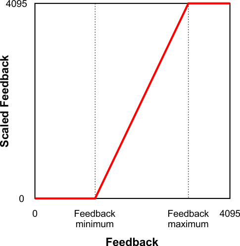 |
This graph shows how the Jrk G2 converts Feedback to Scaled Feedback. |
|---|
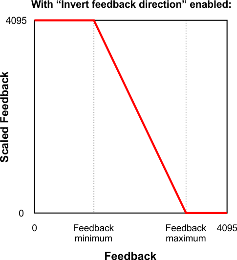 |
This graph shows how the Jrk G2 converts Feedback to Scaled Feedback (with feedback direction inverted). |
|---|
When the “Invert feedback direction” box is not checked, the feedback values are scaled according to these rules:
- Any feedback value greater than the maximum gets scaled to 4095.
- Any feedback value between the minimum and maximum gets scaled to a number between 0 and 4095 (with 0 corresponding to the minimum).
- Any feedback value less than the minimum gets scaled to 0.
When the “Invert feedback direction” checkbox is checked, it changes the scaling so that higher feedback values correspond to lower scaled feedback values. You can think of it as simply switching 0 and 4095 in the rules above.
Feedback error min/max
The “Error max” and “Error min” settings in the “Scaling” box in the “Feedback” tab specify the allowed range of the feedback. If the “Feedback disconnect” error is enabled, and the “Feedback mode” is “Analog voltage” or “Frequency”, and the “Feedback” variable outside of the range specified by those limits, then the Jrk will report a “Feedback disconnect” error. With the default values of these settings (0 and 4095), the feedback value should never be out of range.
Related products


Home | Forum | Blog | Support | Ordering Information | Lists | Distributors | BIG Order Form | About | Contact
© 2001–2026 Pololu Corporation
