Support » Jrk G2 Motor Controller User’s Guide » 7. Details »
7.3. Analog/RC input handling
This section documents the details of how the Jrk G2 reads its analog and RC control inputs in order to set the “Input” variable, and how it scales those inputs in order to set the “Target” variable.
Analog input on SDA/AN
When the Jrk’s “Input mode” is set to “Analog voltage” or the “Always configure SDA/AN for analog input” option is enabled, the Jrk disables its I²C interface and uses the SDA/AN pin as an analog input. Once per PID period, the Jrk takes a configurable number of readings of the SDA/AN pin. The “Analog samples” option in the “Input” tab controls how many readings to take. The Jrk has a 10-bit analog-to-digital converter (ADC), so each reading is a number between 0 and 1023. These readings are added together and bit-shifted appropriately to get a number between 0 and 65,472 which is stored in the “Analog reading SDA” variable, which can be read from the Jrk over USB, serial, or I²C.
If the “Input mode” is set to “Analog voltage” then the Jrk will set its “Input” variable to be equal to the “Analog reading SDA” variable divided by 16. An input value of 0 roughly corresponds to a voltage of 0 V, while an input value of 4092 roughly corresponds to the voltage on the Jrk’s 5V pin.
The “Detect disconnect with power pin (SCL)” option, which is only available when the “Input mode” is set to “Analog voltage”, causes the Jrk to drive the SCL pin low once per PID period after measuring SDA/AN. If the voltage on the SDA/AN pin does not drop by at least a factor of two while SCL is low, then the Jrk reports an “Input disconnect” error (if that error is enabled). The SCL pin drives high at other times.
By default, the SDA/AN input does not have a pull-up resistor, but you can enable one by checking the “Enable pull-up for analog input on SDA/AN” option in the “Advanced” tab.
Pulse measurement on the RC pin
The Jrk measures the width of RC pulses on its RC input pin. The signal on the RC pin should look like the waveform shown below:
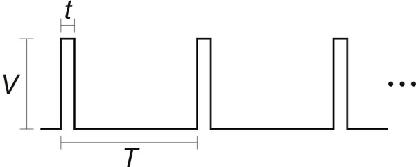 |
The signal should be low (0 V) normally and have periodic pulses with an amplitude (V) of at least 2 V. The width of the pulses (t) should be between 200 µs and 2700 µs. The period of the signal (T), should be at most 100 ms, and the there is no particular lower limit. When the Jrk has received three good pulses in a row, it writes the width of the latest pulse to the “RC pulse width” variable in units of 1/12 µs. The “RC pulse width” variable can be read from the Jrk over USB, serial, or I²C.
If the Jrk goes more than 100 ms without receiving a good pulse, it will change the “RC pulse width” variable to 0 to indicate that the RC signal has been lost. Similarly, if the Jrk goes more than 500 ms without receiving three good pulses in a row, it will change the “RC pulse width” variable to 0.
If the “Input mode” is set to “RC pulse width” then the Jrk will set its “Input” variable to be equal to the “RC pulse width” variable divided by 8, so the “Input” variable will have units of 2/3 µs. The Jrk will also report an “Input invalid” error if that error is enabled and the RC signal has been lost.
RC and analog input scaling
The settings in the “Scaling” box of the “Input” tab determine how the “Input” variable is scaled to compute the “Target” variable. The graphs below illustrate this mapping:
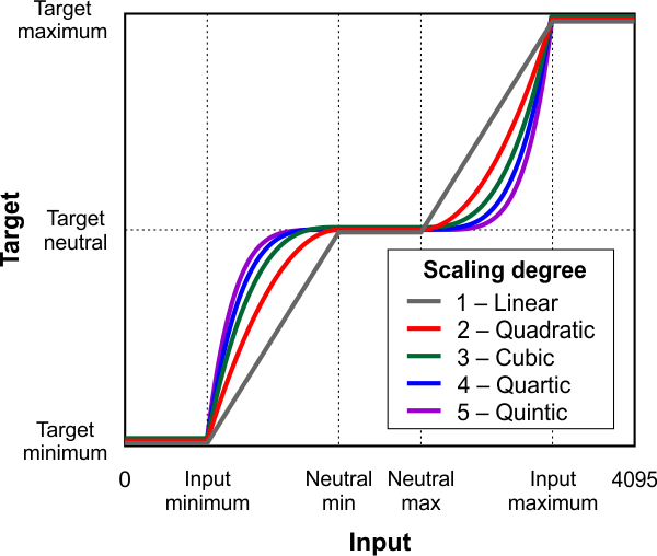 |
This graph shows how the RC/analog input of the Jrk G2 is scaled to produce a target position or target velocity (input direction not inverted). |
|---|
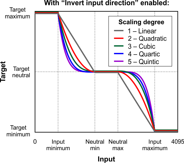 |
This graph shows how the RC/analog input of the Jrk G2 is scaled to produce a target position or target velocity (input direction inverted). |
|---|
When the “Invert input direction” box is not checked, the input values are mapped to output/target values according to these rules:
- Any input value greater than the input maximum gets mapped to the target maximum.
- Any input value between the input neutral max and the input maximum gets mapped to a number between the target neutral value and the target maximum.
- Any input value between the input neutral min and input neutral max gets mapped to the target neutral value.
- Any input value between the input minimum and the input neutral min gets mapped to a number between the target minimum and target neutral value.
- Any input value less than the input minimum gets mapped to the target minimum.
When the “Invert input direction” checkbox is checked, it changes the scaling so that higher input values correspond to lower target values. You can think of it as simply switching the target maximum and target minimum in the rules above.
The “Degree” of the scaling can be set to “1 – Linear”, “2 – Quadratic”, “3 – Cubic”, “4 – Quartic”, or “5 – Quintic”. With the default setting of “1- Linear”, the scaling function is linear. If you choose a higher scaling degree, then the Jrk uses a higher-degree polynomial function, which can give you finer control when the input is closer to its neutral position. With linear scaling, if the input is one quarter (1/4) of the way from the input neutral max to the input maximum, the target will be one quarter (1/4) of the way from the target neutral value to the target maximum. With quadratic scaling, the target would be one sixteenth (1/16) of the way from the target neutral value to the target maximum. With cubic scaling, the ratio would be 1/64, and so on.
The “Input” and “Target” variables are always between 0 and 4095, and each input scaling parameter must also be between 0 and 4095.
Input error min/max
The “Error max” and “Error min” settings in the “Scaling” box in the “Input” tab specify the allowed range of the input. If the “Input disconnect” error is enabled, and the “Input mode” is “Analog voltage” or “RC”, and the “Input” variable outside of the range specified by those limits, then the Jrk will report an “Input disconnect” error. With the default values of these settings (0 and 4095), the input value should never be out of range.
Related products


Home | Forum | Blog | Support | Ordering Information | Lists | Distributors | BIG Order Form | About | Contact
© 2001–2026 Pololu Corporation
