Support » Jrk G2 Motor Controller User’s Guide » 6. Setting up the control method »
6.5. Setting up RC control
This section explains how to set up the Jrk G2 to read a standard hobby RC pulse input and calculate its “Target” variable from that. Please note that this is different from setting up frequency feedback using pulse timing, which is documented in Section 5.3.
If you have not done so already, you should follow the instructions in Section 4.3 to configure and test your motor, and follow the instructions in the appropriate part of Section 5 to set up your desired feedback method.
The Jrk’s RC input accepts the same kind of signal that is used to control standard hobby RC servos, making it compatible with RC receivers. The signal should be low (0 V) by default, with regular 5 V pulses that last between 1 ms and 2 ms typically (though the Jrk can accept a wider range of roughly 0.2 ms to 2.7 ms). The Jrk can measure the RC signal and set the “Input” variable equal to the RC pulse width, in units of 2/3 µs.
With the system unpowered, connect your RC receiver to the Jrk’s GND, 5V, and RC pins.
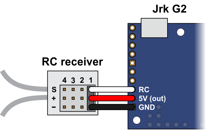 |
Connecting an RC receiver to the Jrk G2. |
|---|
In this configuration, the RC receiver will be powered by the Jrk’s 5 V regulator via the 5V output pin. If you want to power the receiver from another power source instead, you should not connect the Jrk’s 5V pin to it as doing so would short the two sources together and could damage the Jrk or receiver.
If the Jrk gets reset when you plug in your RC receiver, it might be because the in-rush current of the receiver is too much for the Jrk’s 5V line and causes its voltage to drop temporarily. As general good engineering practice, we recommend making and breaking electrical connections only while your devices are powered off.
Now connect the Jrk to your computer via USB. In the Jrk G2 Configuration Utility software, go to the “Input” tab and set the “Input mode” to “RC”. You should also go to the “Errors” tab and set the “Input invalid” and “Input disconnect” errors to enabled. Click “Apply settings”.
Go to the “Input” tab, and in the “Scaling” box, click “Input setup wizard…”. This wizard will help you measure the neutral, maximum, and minimum positions of your RC signal. When the wizard is finished, it will set seven of the input scaling parameters (input error maximum, input maximum, input neutral maximum, input neutral minimum, input minimum, input error minimum, and invert input direction) appropriately so that neutral RC signals get mapped to the target neutral value, the maximum RC signal gets mapped to the target maximum, and the minimum RC signal gets mapped to the target minimum.
The input setup wizard does not set the target maximum, target neutral, and target minimum values, so you will need to set them yourself:
- If you are using open-loop speed control (“Feedback mode” is “None”), you should probably set those values to 2648, 2048, and 1448, so that you can use the full range of your RC input. This assumes you also you want to drive your motor at full speed in both directions. If that is not the case, you can move the target maximum and/or target minimum values closer to 2048 to reduce the speed and use more of the range of your RC input.
- If you are using analog feedback, the default values of 4095, 2048, and 0, will generally be pretty good.
- If you are using frequency feedback (speed control), you will probably want to set those values to 2048 + F, 2048, and 2048 − F, where F corresponds to the maximum frequency (speed) you want to command the Jrk to obtain (see Section 5.3).
Click “Apply settings” to save these settings to the Jrk.
Now turn on motor power and click “Run motor” to start your system. As you move your input from end to the other, you should see your system moving through its full range of speeds or positions.
Finally, check the “Scaling degree” parameter. The default is “1 – Linear”. If you want finer control near the neutral point of your input and coarser control near the ends, you can change it to one of the higher settings.
For details about how the input scaling works, see Section 7.3.
Related products


Home | Forum | Blog | Support | Ordering Information | Lists | Distributors | BIG Order Form | About | Contact
© 2001–2026 Pololu Corporation
