Support »
Pololu P-Star User’s Guide
View document on multiple pages.
You can also view this document as a printable PDF.
- 1. Overview
- 2. Contacting Pololu
- 3. P-Star 25K50 Micro
- 4. P-Star 45K50 Mini SV
- 5. Getting started
- 6. The P-Star Bootloader
- 7. Programming using the PICkit 3
- 8. Compiling P-Star examples
- 9. Compiling a USB application with M-Stack
- 10. Compiling a program with MPLAB X and MPASM
- 11. Compiling a program with PICBASIC PRO
1. Overview
 |
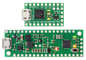
P-Star 25K50 Micro (top) and P-Star 45K50 Mini SV (bottom). |
|---|
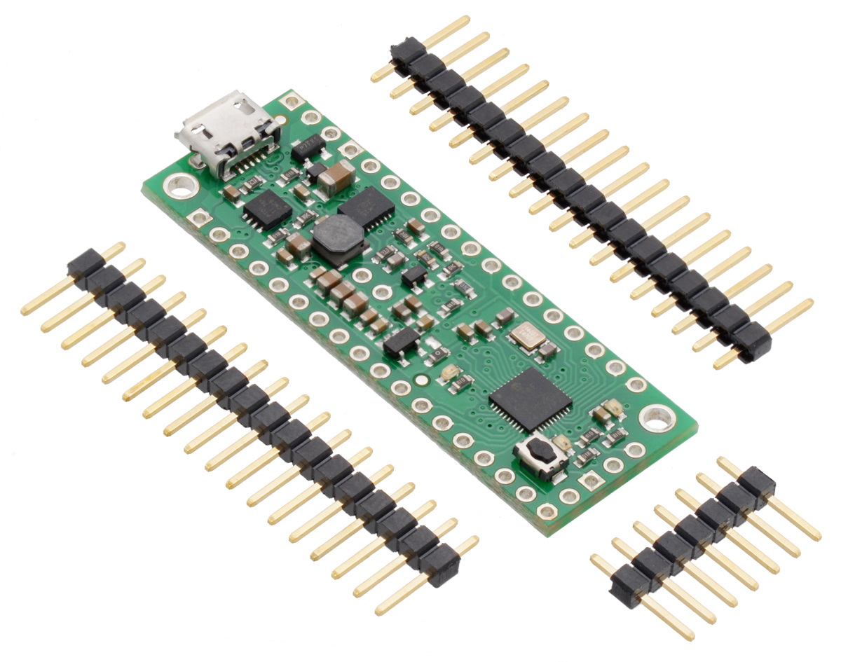
The Pololu P-Star microcontroller boards are a family of general-purpose programmable modules based on the PIC18F25K50 and PIC18F45K50 microcontrollers from Microchip, which have 32 KB of flash program memory, 2 KB of RAM, and built-in full-speed USB functionality. The P-Stars add on-board components and connectors that support the microcontroller and make it easier to use. Each board ships with a USB bootloader that makes it easy to load new programs without using an external programmer.
The P-Star requires a USB A to Micro-B cable (not included) to connect to a computer.
Features and specifications
- Programmable Microchip PIC18F25K50 or PIC18F45K50 microcontroller
- 32 KB flash (8 KB used by bootloader, leaving 24 KB available for user program by default)
- 2 KB SRAM
- 256 bytes of EEPROM
- Native full-speed USB (12 Mbps)
- 2 PWM output signals (one of which can be sent to four different pins)
- 5-bit digital-to-analog converter (DAC) output
- 5 V logic voltage
- Internally clocked at 48 MHz, resulting in execution speeds up to 12 million instructions per second (MIPS)
- Precision 16 MHz crystal
- Three user-controllable LEDs
- USB Micro-B connector
- Can be powered from USB or external source regulated to 5 V by on-board regulator
- Reverse-voltage protection on external power input
- Ships with a proprietary USB bootloader developed by Pololu for the P-Star (see Section 6)
- Bootloader is usable from Windows, Linux, and Mac OS X with open source software
- No external programmer required
- Compatible with standard Microchip compilers, development tools, and programmers
P-Star comparison table
 |
 | |
| P-Star 25K50 Micro | P-Star 45K50 Mini SV | |
|---|---|---|
| Microcontroller: | PIC18F25K50 | PIC18F45K50 |
| User I/O lines: | 19 | 30 |
| Analog inputs: | 14 | 25 |
| Reset button: |  |
|
| Operating voltage: | 5.5 V to 15 V | 5 V to 36 V |
| Regulator type: | linear | switching step-down |
| Regulated current:(1) | 100 mA | 500 mA |
| Auxiliary 3.3 V regulator: | |
|
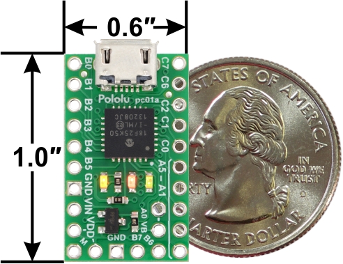
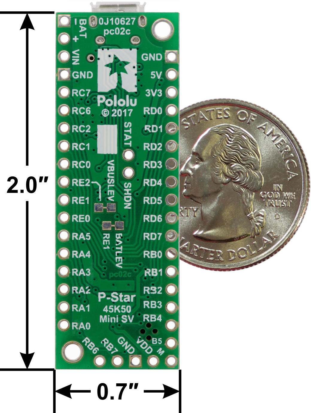
| Dimensions: | 1″ × 0.6″ | 2.0″ × 0.7″ |
| Weight:(2) | 1.3 g | 3.5 g |
1 These values are rough approximations for comparison purposes. Available current depends on input voltage, current consumed by the board, ambient conditions, and regulator topology.
2 Without included optional headers.
1.1. Supported operating systems
The Pololu USB Bootloader Utility (p-load), which is used to load programs onto the P-Star, works on Windows Vista, Windows 7, Windows 8, Windows 8.1, Windows 10, Linux, and macOS. The utility does not work on Windows XP. The source code is available, so it should be possible to port it to more operating systems.
2. Contacting Pololu
 |
We would be delighted to hear from you about any of your projects and about your experience with the P-Star. You can contact us directly or post on our forum. Tell us what we did well, what we could improve, what you would like to see in the future, or anything else you would like to say!
3. P-Star 25K50 Micro
 |
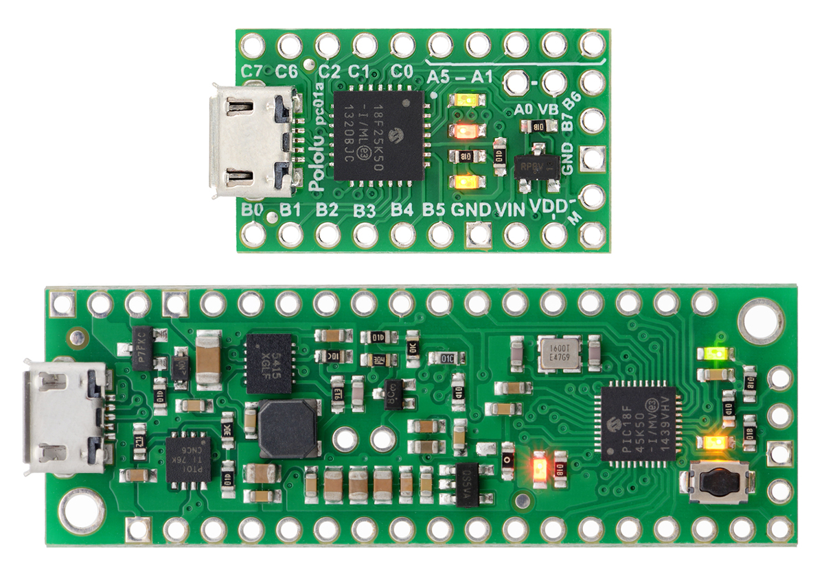
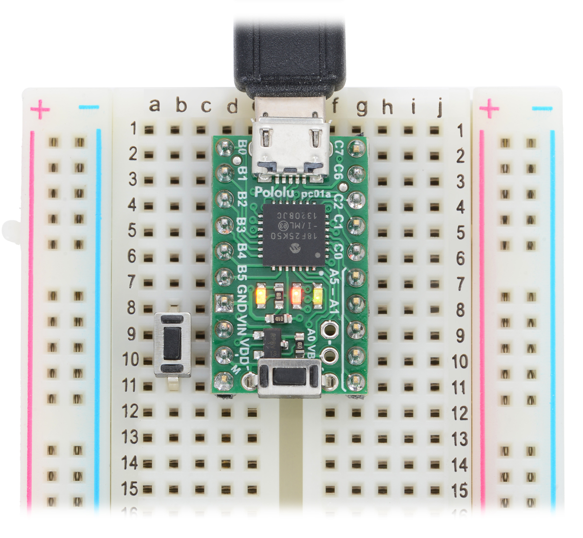
P-Star 25K50 Micro, top view. |
|---|
3.1. P-Star 25K50 Micro pinout and components
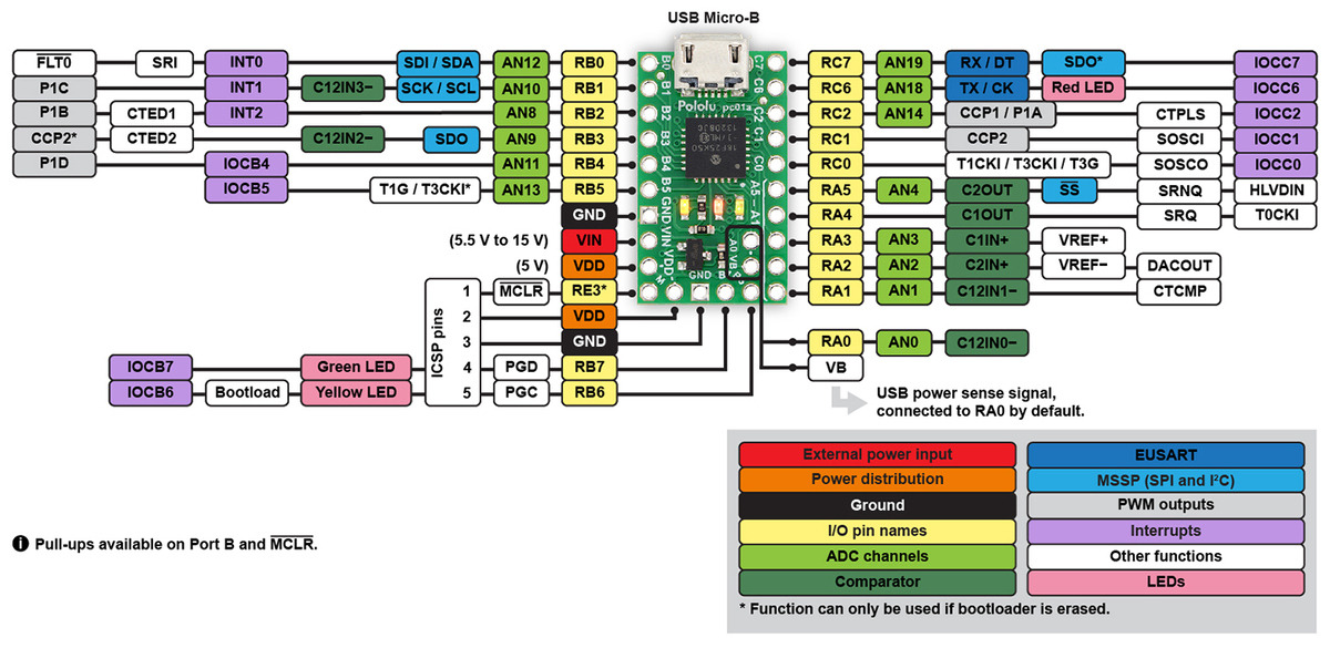 |
P-Star 25K50 Micro pinout diagram. |
|---|
This diagram identifies the I/O and power pins on the P-Star 25K50 Micro. The diagram is also available as a printable PDF (161k pdf). For more information about the PIC18F25K50 microcontroller and its peripherals, see Microchip’s PIC18F25K50 documentation.
LEDs
The P-Star 25K50 Micro has three indicator LEDs. These LEDs are connected in the same way on all P-Stars.
The yellow LED is connected to RB6. Driving this pin high turns on the LED. In bootloader mode, the bootloader drives this line high to turn on the LED (see Section 6.4) but never drives it low. If this line is high when the microcontroller starts up, the microcontroller will go into bootloader mode. A button can be connected to RB6 as described in Section 5.2. RB6 has an on-board pull-down resistor to ensure that its voltage goes all the way down to 0 V when not being driven.
The green LED is connected to RB7, and lights when the pin is driven high. In bootloader mode, the bootloader drives this line high to turn on the LED (see Section 6.4) but never drives it low.
The red LED is connected to RC6, and lights when the pin is driven low. RC6 is the microcontroller’s serial TX line, so the red LED serves as an indicator for when the board is transmitting serial data. If you are not using serial, the LED can be used as a normal LED. To avoid interference with connected serial devices, the bootloader does not use this LED.
Connectors
The P-Star includes a USB Micro-B connector that can be used to connect to a computer’s USB port via a USB A to Micro-B cable (not included). The USB connection can be used to transmit and receive data from the computer, and a preloaded USB bootloader makes it possible to program the board over USB. The USB connection can also provide power to the P-Star.
The board also has five pins arranged so that they can be directly plugged into a standard In-Circuit Serial Programming (ICSP) connector, such as the one found on the PICkit 3. More information about programming with the PICkit 3 can be found in Section 7. The five pins are: MCLR, VDD, GND, RB7/PGD, and RB6/PGC. The MCLR pin is pin 1.
Power
The P-Star 25K50 Micro can either be powered directly from the USB 5 V supply or from a separate source on the VIN pin. The board features a power selection circuit that allows both USB and VIN to be connected at the same time; if this is done, the P-Star will draw power from VIN.
USB power input: The P-Star can be powered from the USB 5 V bus voltage (VBUS) if it is connected to a USB cable. It will draw power from USB only if VIN is disconnected. A resettable PTC fuse on VBUS makes it less likely for the P-Star (and the connected computer or other device) to be damaged if too much current is drawn from the USB connection.
VIN power input: The P-Star can be powered from VIN if you connect a 5.5 V to 15 V power supply (such as a battery or wall power adapter) to the VIN and GND pins, with the positive terminal connected to VIN.
VDD: This pin provides access to the board’s 5 V supply, which comes from either the USB 5 V bus voltage or a low-dropout (LDO) regulator on VIN, depending on which power source is connected. The regulator can supply up to 100 mA, although some of this is used by the board itself or used to provide current for the GPIO pins.
To ensure that VDD is a stable 5 V, you must either disconnect VIN and use USB to power the board or supply a VIN of at least 5.5 V. When VIN drops below 5.5 V, VDD will fall (even with USB connected). However, the P-Star will continue to run with VDD below 5 V, and it can operate from VIN alone with VIN as low as 3.2 V to 3.8 V, depending on the load and temperature. With USB connected, VDD will drop at worst to about 4.5 V, and the P-star will continue operating no matter how low VIN is.
When the P-Star 25K50 Micro is being powered through VIN, regardless of whether USB is connected, the sum of the 5V output current, GPIO output current, and current used by the board itself (typically about 18 mA) should not exceed the 100 mA that the regulator can provide.
|
|
USB power sensing
The VB pin, located on the interior of the board, is connected to the USB 5 V bus voltage through a 1 kΩ resistor. By default, the VB pin is also connected to the RA0 pin through a cuttable trace on the bottom of the board between the two pins. This means that RA0 can be used as a digital or analog input to detect the presence of USB power. Cutting the trace between the VB and RA0 pins allows RA0 to be used for other purposes.
Crystal
The P-Star 25K50 Micro has a precision 16 MHz crystal. By default, this crystal is used to provide a clock signal for the microcontroller and its peripherals.
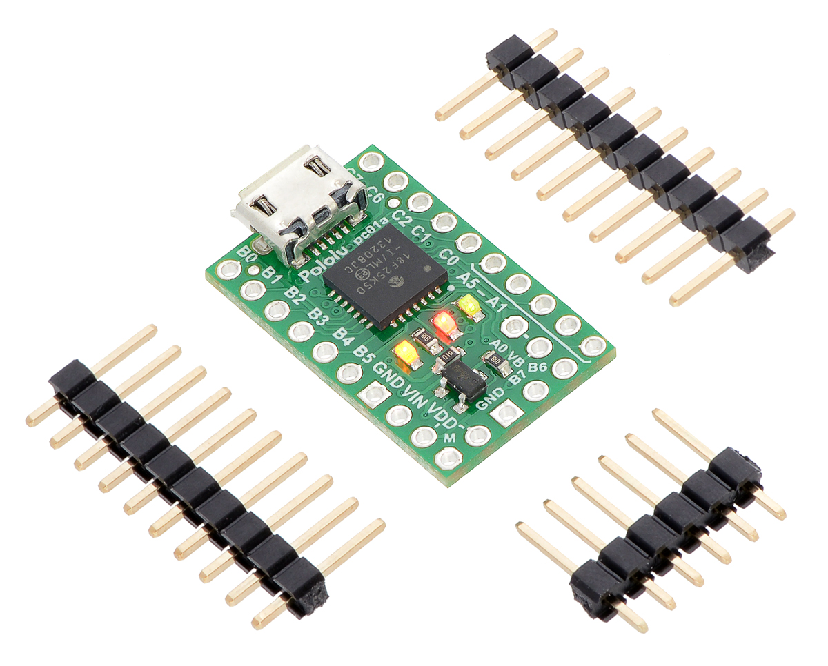
Included hardware
Two 1×10-pin breakaway 0.1″ male headers and one 1×6-pin breakaway 0.1″ male header are included with the P-Star 25K50 Micro. These header pins can be soldered in to use the board with perfboards, breadboards, or 0.1″ female connectors.
|
|
3.2. P-Star 25K50 Micro schematic and dimensions
Schematic diagram
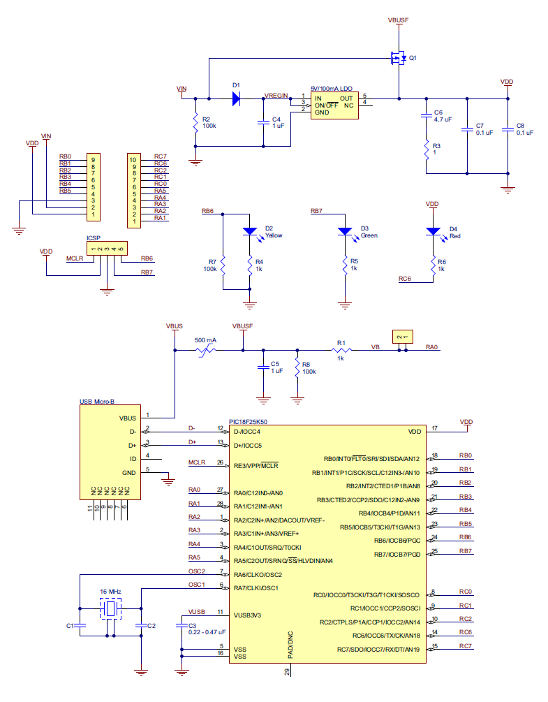 |
P-Star 25K50 Micro schematic diagram. |
|---|
This schematic is also available as a PDF: P-Star 25K50 Micro schematic diagram (414k pdf).
Dimension diagram
A dimension diagram is available as a PDF: P-Star 25K50 Micro dimension diagram (202k pdf)
4. P-Star 45K50 Mini SV
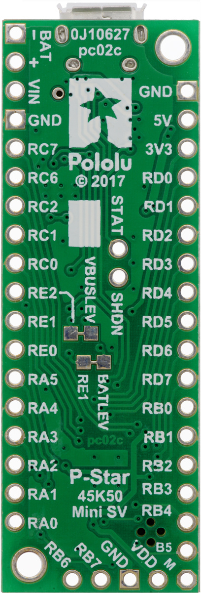 |
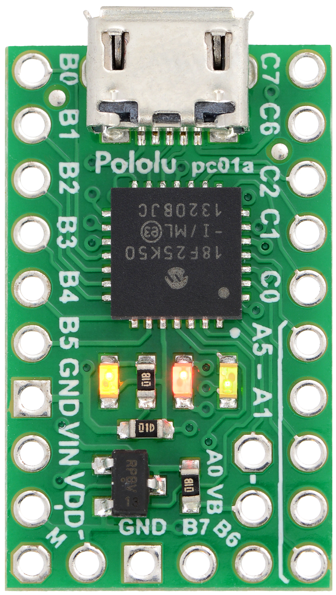
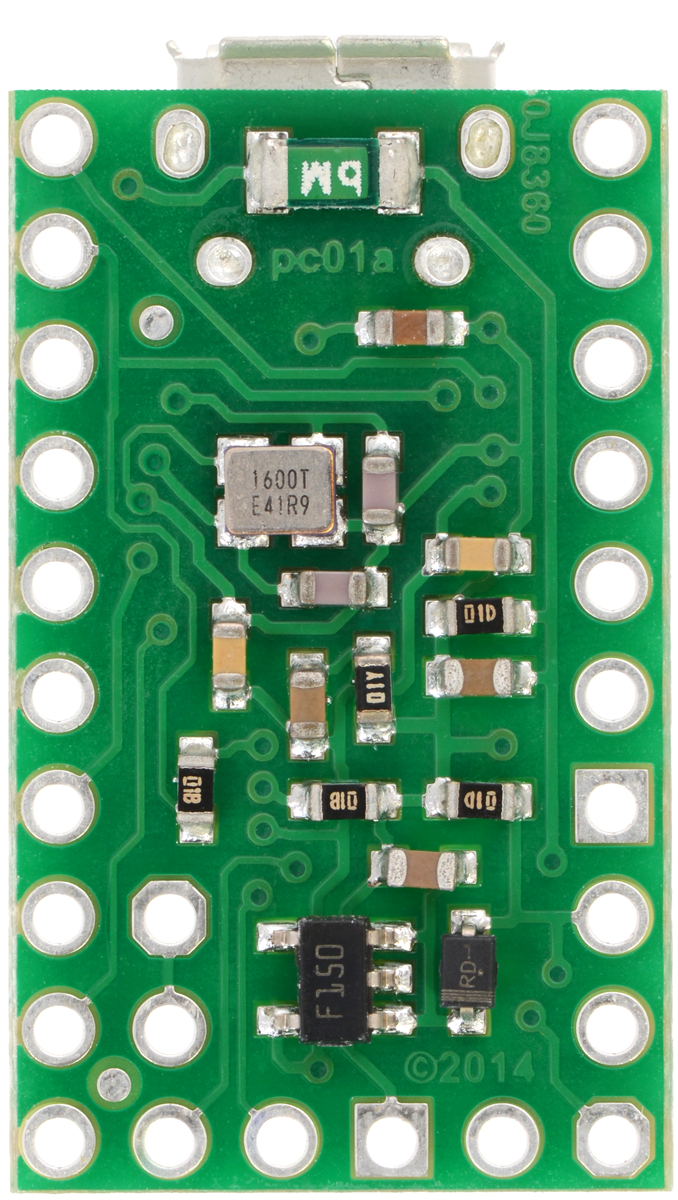
P-Star 45K50 Mini SV, bottom view. |
|---|
4.1. P-Star 45K50 Mini SV pinout and components
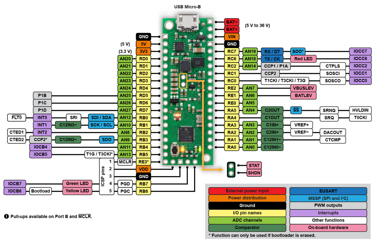 |
P-Star 45K50 Mini SV pinout diagram. |
|---|
This diagram identifies the I/O and power pins on the P-Star 45K50 Mini. The diagram is also available as a printable PDF (547k pdf). For more information about the PIC18F45K50 microcontroller and its peripherals, see Microchip’s PIC18F45K50 documentation.
LEDs
The P-Star 45K50 Mini has three indicator LEDs. These LEDs are connected in the same way on all P-Stars.
The yellow LED is connected to RB6. Driving this pin high turns on the LED. In bootloader mode, the bootloader drives this line high to turn on the LED (see Section 6.4) but never drives it low. If this line is high when the microcontroller starts up, the microcontroller will go into bootloader mode. A button can be connected to RB6 as described in Section 5.2. RB6 has an on-board pull-down resistor to ensure that its voltage goes all the way down to 0 V when not being driven.
The green LED is connected to RB7, and lights when the pin is driven high. In bootloader mode, the bootloader drives this line high to turn on the LED (see Section 6.4) but never drives it low.
The red LED is connected to RC6, and lights when the pin is driven low. RC6 is the microcontroller’s serial TX line, so the red LED serves as an indicator for when the board is transmitting serial data. If you are not using serial, the LED can be used as a normal LED. To avoid interference with connected serial devices, the bootloader does not use this LED.
Connectors
The P-Star includes a USB Micro-B connector that can be used to connect to a computer’s USB port via a USB A to Micro-B cable (not included). The USB connection can be used to transmit and receive data from the computer, and a preloaded USB bootloader makes it possible to program the board over USB. The USB connection can also provide power to the P-Star.
The board also has five pins arranged so that they can be directly plugged into a standard In-Circuit Serial Programming (ICSP) connector, such as the one found on the PICkit 3. More information about programming with the PICkit 3 can be found in Section 7. The five pins are: MCLR, VDD, GND, RB7/PGD, and RB6/PGC. The MCLR pin is pin 1.
Power
The P-Star 45K50 Mini SV can either be powered directly from the USB 5 V supply or from an external voltage source between 5 V and 36 V, which is regulated to 5 V by a 500 mA ISL85415 switching step-down (buck) converter from Intersil. (We also make a standalone regulator based on this integrated circuit.). The board also has an auxiliary linear regulator producing 3.3 V.
The board’s power selection circuit uses the TPS2113A power multiplexer from Texas Instruments to choose whether its 5 V supply is sourced from USB or an external supply via the regulator, allowing both sources to be connected at the same time and enabling the P-Star to safely and seamlessly transition between them. The TPS2113A is configured to select external power unless the regulator output falls below about 4.5 V. If this happens, it will select the higher of the two sources, which will typically be the USB 5 V bus voltage if the P-Star is connected to USB. The currently selected source is indicated by the STAT pin in the middle of the board; this pin is an open-drain output that is low if the external power source is selected and high-impedance if the USB supply is selected. The current limit of the TPS2113A is set to about 1.9 A. For more information about the power multiplexer, see the TPS2113A datasheet (1k redirect).
In some situations, it might be undesirable for the P-Star 45K50 Mini to draw power from an external source when it is connected to USB. If this is the case, the regulator can be disabled by driving the regulator shutdown pin, SHDN, high; this shuts down the regulator and causes the power mux to fall back to USB power. For example, this could allow a battery-powered device to turn off the regulator and avoid draining its battery while it is connected to a computer.
USB power input: The P-Star can be powered from the USB 5 V bus voltage (VBUS) if it is connected to a USB cable. It will draw power from USB only if its external voltage source is disconnected.
Reverse-protected power inputs: The BAT+ and BAT− are power inputs with reverse-voltage protection. These are the recommended pins to use when connecting an external power supply because they allow the P-Star’s reverse-voltage protection circuit to help prevent it from being damaged by accidentally reversed power connections.
VIN power output (or alternative input): When power is supplied through the BAT pins, the VIN pin can be used as an output to supply reverse-protected power to other devices. Alternatively, the external supply can be connected directly between VIN and GND, bypassing the reverse-voltage protection.
5V power output: This pin provides access to the board’s 5 V supply, which comes from either the USB 5 V bus voltage or the on-board switching regulator, depending on which power sources are connected and enabled.
3V3 power output: This pin gives access to the output of the on-board 3.3 V linear regulator, which can provide a few hundred milliamps of current.
VDD: The VDD pin powers the microcontroller and is connected directly to the 5V power output.
|
|
USB power sensing
The voltage from USB (VBUS) powers a voltage divider that produces a voltage called VBUSLEV that is 91% of VBUS. By default, VBUSLEV is connected to the RE2 pin through a cuttable trace on the bottom of the board. This means that RE2 can be used as a digital or analog input to detect the presence of USB power. Cutting the trace between the RE2 and VBUSLEV pads on the bottom of the board allows RE2 to be used for other purposes. You can use solder to reconnect the two nodes.
External power sensing
The voltage on VIN powers a voltage divider that produces a voltage called BATLEV that is 9% of VIN. By default, BATLEV is connected to the RE1 pin through a cuttable trace on the bottom of the board. This means that RE1 can be used as an analog input to measure the external power supply voltage. Cutting the trace between the RE1 and BATLEV pads on the bottom of the board allows RE1 to be used for other purposes. You can use solder to reconnect the two nodes.
Reset button
The pushbutton on the P-Star 45K50 Mini resets the microcontroller when it is pressed.
Crystal
The P-Star 45K50 Mini has a precision 16 MHz crystal. By default, this crystal is used to provide a clock signal for the microcontroller and its peripherals.
Included hardware
Two 1×18-pin breakaway 0.1″ male headers and one 1×7-pin breakaway 0.1″ male header are included with the P-Star 45K50 Mini. These header pins can be soldered in to use the board with perfboards, breadboards, or 0.1″ female connectors.
|
|
4.2. P-Star 45K50 Mini SV schematic and dimensions
Schematic diagram
A schematic diagram is available as a PDF: P-Star 45K50 Mini SV schematic diagram (252k pdf).
Dimension diagram
A dimension diagram for the P-Star 45K50 Mini SV will be available in this section soon.
5. Getting started
5.1. Installing p-load and drivers
To use the P-Star’s USB bootloader, you will need to install a command-line utility called the Pololu USB Bootloader Utility. This program is also known as “p-load” because that is the command used to run it from a command prompt.
Windows
If you are using Microsoft Windows, you should download and install the Pololu USB Bootloader Utility (p-load) for Windows (1MB msi). This includes the p-load executable and the drivers necessary for the P-Star bootloader. During the installation, Windows will ask you if you want to install the drivers. Click “Install”.
After the installation has finished, your computer will automatically detect any P-Star that is in bootloader mode and use the proper drivers for it. You should see an entry for the P-Star bootloader in the “Universal Serial Bus devices” category or the “Pololu USB Devices” category in your Device Manager. The latest drivers use the “Universal Serial Bus devices” category, but if your P-Star was set up with an older driver, then it might still be in “Pololu USB Devices”.
Mac OS X
If you are using Mac OS X, you should download and install the Pololu USB Bootloader Utility (p-load) for Mac OS X (87k pkg). The latest version of the utility software requires Mac OS X 10.11 or later. For older versions of Mac OS X, use p-load 1.0.0 (33k dmg) instead (which only supports the P-Star 25K50).
Linux
If you are using Linux, you should download and install the appropriate version of the Pololu USB Bootloader Utility below:
- Pololu USB Bootloader Utility (p-load) for Linux (x86) (478k xz) – works on 32-bit and 64-bit systems
- Pololu USB Bootloader Utility (p-load) for Linux (Raspberry Pi) (374k xz) – works on the Raspberry Pi and might work on other ARM Linux systems
Run tar -xvf p-load-*.tar.xz to extract the software, and then follow the directions in README.txt to install it.
Source code
The Pololu USB Bootloader Utility source code is also available, so you can build the utility yourself.
5.2. Getting into bootloader mode
The P-Star comes with a USB bootloader that allows you to load new programs onto the P-Star over USB without using an external programmer. To use the bootloader, you will first need to get the P-Star into bootloader mode.
When the P-Star is in bootloader mode, the yellow LED should be on and the green LED should be blinking. If the P-Star has never been programmed, or if the user application has been erased, then the P-Star will automatically go into bootloader mode when it is powered on. Otherwise, you will have to use one of the procedures below to get it into bootloader mode.
Starting the bootloader with a wire or button
The P-Star will go into bootloader mode if the RB6 line is high immediately after a reset. This will work no matter what type of application is loaded on the P-Star.
For example, if your P-Star is only powered from USB, you could hold a wire between VDD and RB6 while you are plugging the P-Star into USB in order to get it into bootloader mode.
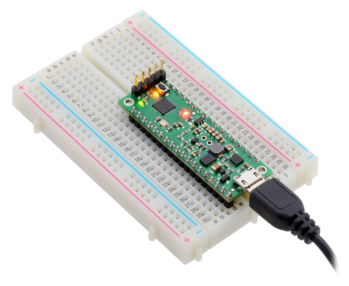
Another option is to connect a bootloader button between VDD and RB6 and a reset button between GND and MCLR as shown in the picture below, and reset the P-Star while you are holding down the bootloader button. The picture below shows one way to hook up those two buttons to a P-Star 25K50 Micro on a breadboard, using our two of our mini pushbutton switches. If you have a P-Star 45K50 Mini, you can do the same thing, except it is probably more convenient to use the reset button on the board instead of connecting an external one.
 |
P-Star 25K50 Micro on a breadboard with a reset button (left) and a bootloader button (on-board). |
|---|
The bootloader button can be used for other purposes while your application is running. However, be careful to never drive the RB6 line low, or else pressing the button could cause a short circuit.
Starting the bootloader from your application
The bootloader can also be started by the application without requiring a reset. To do this, the application can simply jump to address 4 using the assembly instruction goto 4. If the application uses USB, it should disable the USB module by clearing USBEN and then wait for at least 100 ms before starting the bootloader in order to give the computer time to detect that the application has disconnected.
For convenience, we recommend that any P-Star applications with a USB interface implement a USB command for starting the bootloader. This would allow you to get into bootloader mode, upload the new firmware, and run it, entirely using USB and not needing any physical interaction with the board. For example, an application with a USB virtual COM port could listen for a special baud rate to be set by the computer.
5.3. Compiling a program with MPLAB X and XC8
The P-Star can be programmed using standard development tools from Microchip. This section explains how to get started programming the P-Star in the C language using MPLAB X and XC8. MPLAB X a free integrated development (IDE) from Microchip for programming their PIC microcontrollers. XC8 is a C compiler from Microchip for 8-bit PICs. Both programs run on Windows, Max OS X, and Linux.
- Download and install the latest versions of MPLAB X and XC8 .
- Find “MPLAB X IDE” in your Start Menu and run it.
- From the File menu, select “New Project”.
- On the first screen of the New Project wizard, select the “Microchip Embedded” category and then select “Standalone Project”. Click “Next”.
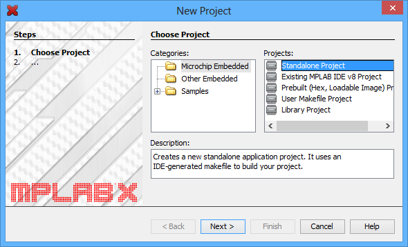 |
- For the Device, type the name of the microcontroller on your P-Star, which is either “PIC18F25K50” or “PIC18F45K50”. Click “Next”.
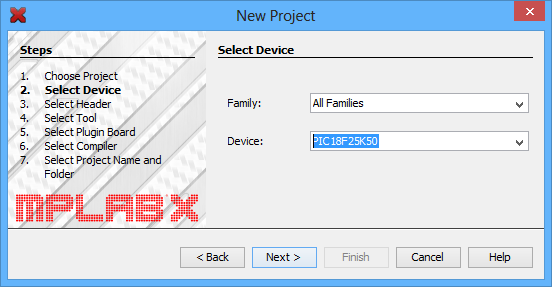 |
- On the “Select Tool” screen, you can select “PICkit 3” but this choice does not matter because we will not use MPLAB X to the load the program onto the board.
- For the compiler, select XC8.
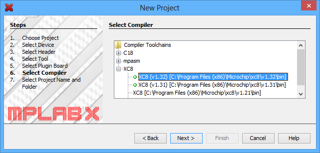 |
- For the Project Name, choose something like “p-star1”, and choose the folder you want it to be in. Click “Finish” to create the project.
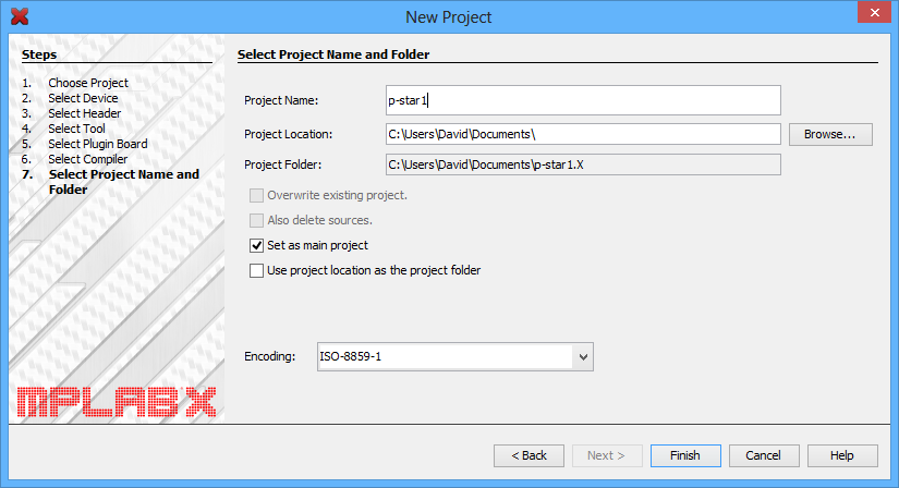 |
- We need to configure the project’s linker setting to properly account for the P-Star’s bootloader, which takes up the first 8 KB of flash memory. In the “File” menu, select “Project Properties”. In the “XC8 linker” category, select the “Additional options” sub-category. In the “Codeoffset” box enter 0x2000, which is 8*1024 in hex. Click “OK.”
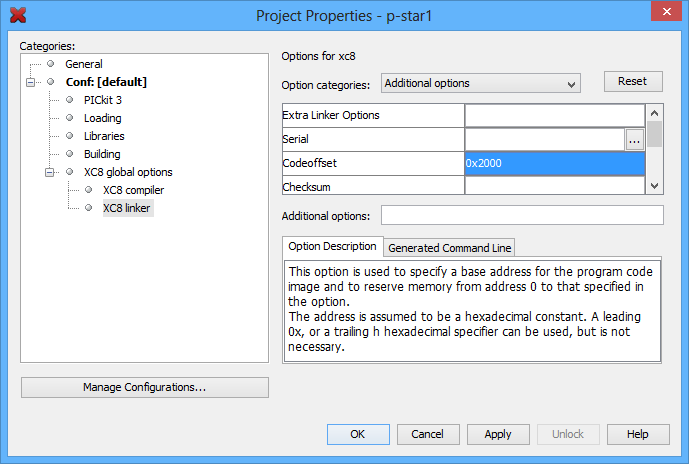 |
- Now we need to create the C source file. Locate the “Projects” pane. If the “Projects” pane is not visible, you can open it by opening the “Window” menu and selecting “Projects”. Left-click the “+” sign next to “Source Files” to expand it and verify that your project has no source files yet. Then right-click on “Source Files”, select “New”, and then select “C Source File…”.
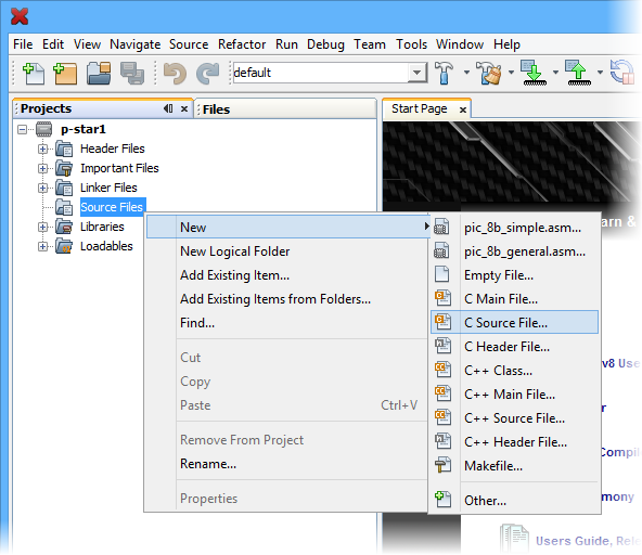 |
- Choose a file name like “main” and then click Finish.This should create a new file named “main.c” and open it for editing.
- Copy and paste the following code into main.c:
#include <xc.h>
#define _XTAL_FREQ 48000000

#define LED_GREEN(v) { TRISB7 = !(v); }
#define LED_YELLOW(v) { TRISB6 = !(v); }
#define LED_RED(v) { TRISC6 = !(v); }

void main()
{
    // Set up the LEDs
    LATB7 = 1;
    LATB6 = 1;
    LATC6 = 0;

    /* Enable Timer 0 as a 16-bit timer with 1:256 prescaler: since
       the instruction speed is 12 MHz, this overflows about every 1.4
       seconds. */
    T0CON = 0b10000111;

    while(1)
    {
        TMR0L; // trigger an update of TMR0H

        // Blink the green LED with a period of 1.4 s
        LED_GREEN(TMR0H >> 7 & 1);

        // Blink the yellow LED with a period of 0.7 s
        LED_YELLOW(TMR0H >> 6 & 1);

        // Blink the red LED with a period of 0.35 s
        LED_RED(TMR0H >> 5 & 1);
    }
}
- To compile the code, open the “Production” menu and select “Build Main Project”.
- The “Output” pane should now show the build output from MPLAB X. This includes all the command-line arguments passed to XC8 to compile the program, and all the output from the compiler. You should see several instances of warnings similar to “warning: (1311) missing configuration setting for config word 0x300000, using default”. This is OK, since the P-Star’s configuration bits are set during manufacturing and they cannot be changed using the bootloader.
- One of the last lines of the output should say “Loading code from” and have the full path to the HEX file produced during compilation. This path and filename will be important later when you load the program onto the P-Star.
Where to find more information
For information about the hardware peripherals and registers on the PIC, see the PIC18F25K50/PIC18F45K50 datasheet.
For information about MPLAB X, you can find useful resources under the “Help” menu and in the “docs” directory inside your MPLAB X installation.
For information about XC8, look in the “docs” directory inside your XC8 installation to find its user’s guide.
If you have questions, you can post in Microchip’s XC8 forum or the Pololu Robotics Forum.
5.4. Programming using p-load
The previous sections cover how to install Pololu USB Bootloader Utility (p-load) and the drivers for the P-Star (Section 5.1), how to get the P-Star into bootloader mode (Section 5.2), and how to compile a simple program for the P-Star (Section 5.3). Once all these steps are complete, you are ready to use p-load to write the program to your P-Star.
To do so, open a new command prompt and run a command of the form:
p-load -w HEXFILE
where HEXFILE is the full or relative path to the HEX file you compiled. When you run this command, the output should look something like:
Device:        Pololu P-Star 45K50 Bootloader
Serial number: 00203525
Erasing flash...
Progress: |##########################################################| Done.
Erasing EEPROM...
Progress: |##########################################################| Done.
Writing flash...
Progress: |##########################################################| Done.
Sent command to restart device.
The -w option tells p-load to write the flash and EEPROM memories with the values specified in the HEX file, and then restart the device so that the application can run. The Pololu USB Bootloader Utility has many other options available, and you can see them by running p-load with no arguments.
The p-load utility automatically looks for a supported bootloader connected to the computer via USB and will operate on that bootloader. If you have multiple devices supported by p-load connected to your computer, you must use the -d option followed by the serial number of the device to specify which device you want to write to.
To write to EEPROM, data should be placed in the HEX file starting at address 0xF00000 (0xF00000 corresponds to the first byte of EEPROM). This is compatible with the way XC8 treats EEPROM.
6. The P-Star Bootloader
The P-Star comes with a proprietary bootloader developed by Pololu that uses a native USB protocol. The bootloader allows you to read and write the flash and EEPROM memories of the chip without using an external programmer.
There are two different versions of the P-Star bootloader:
- The P-Star 25K50 Bootloader is used on the P-Star 25K50 Micro.
- The P-Star 45K50 Bootloader is used on the P-Star 45K50 Mini SV.
These versions are essentially the same, but they have different USB product IDs and different USB string descriptors.
6.1. Memory organization
Flash memory sections
The bootloader occupies the first 8 KB (8192 bytes) of the PIC microcontroller’s flash memory. The remaining 24 KB of flash is available for the application. The bootloader places no restrictions on what data can be written to the application section. However, the bootloader will consider the application to be invalid and not allow any code in the application section to run if the first word of the application section (at address 0x2000) is 0xFFFF, which would correspond to a NOP.
Entry and interrupt vectors
The entry vector and interrupt vectors are remapped by the bootloader to the beginning of the application section:
- The application’s entry vector should be placed at 0x2000. This is the location where code will start executing when the application is started.
- The high-priority interrupt vector should be at 0x2008.
- The low-priority interrupt vector should be at 0x2018.
The interrupt vectors can be ignored and those locations can hold normal code if interrupts are not enabled in the application.
The application can start the bootloader by jumping to address 0x0004 using a goto instruction. This method of starting the bootloader does not involve a reset, so the state of the microcontroller matters and certain configurations could cause problems for the bootloader. For example, an application that changes the configuration of the system oscillators will most likely have to revert its changes before starting the bootloader. Also, an application that uses USB should disable the USB module by clearing USBEN and then wait for at least 100 ms before starting the bootloader, in order to give the computer time to detect that the application has disconnected.
The code below is PIC assembly code that shows how these vectors are defined in the bootloader. The two CPU interrupt vectors (0x0008 and 0x0018) each have a goto instruction that jumps directly to the user application. The two entry vectors (0x0000 and 0x0004) each have goto instructions that jump to the appropriate part of the bootloader code.
    org     0x0000              ; CPU reset vector
    goto    powerup             ; Start app or bootloader

    org     0x0004              ; Bootloader launch vector
    goto    powerupBootloader   ; Start bootloader

    org     0x0008              ; CPU high-priority interrupt vector
    goto    0x2008              ; Jump to the application's ISR

    org     0x0018              ; CPU low-priority interrupt vector
    goto    0x2018              ; Jump to the application's ISR
Serial number
The bootloader comes with a unique serial number that is assigned during manufacturing. This serial number is typically an 8-digit decimal number, but in the future we might expand it to have other characters or make it be up to 16 characters long. The serial number is accessible from the application, and applications using USB can expose the serial number as a string descriptor.
Read-only data
Part of the bootloader’s flash memory is used to store some information that can be read by the application:
- Addresses 0x40–0x51 contain the USB device descriptor of the bootloader, as defined in the USB 2.0 Specification.
- Addresses 0x60–0x70 contain the serial number as an ASCII string with a null terminator byte. The extra bytes after the null terminator are all set to zero.
- Addresses 0x80–0xA1 contain the serial number in USB string descriptor format. The extra bytes after the end of the string are all set to zero.
6.2. Startup procedure
Every time the microcontroller powers on or is reset for any reason, the bootloader’s startup code runs. First, the code sets all of the bytes in RAM to 0, which can help make the behavior of the bootloader and the application more predictable. Second, it reads the first word of the application’s flash section. If that word is 0xFFFF, it considers the application to be missing and it runs the bootloader. Third, it reads pin RB6 and runs the bootloader if RB6 is high. Finally, if none of these tests have caused it to go into bootloader mode, it runs the application.
Going through this startup procedure is the only way that the application can run.
 |
The startup logic for the P-Star USB bootloader. |
|---|
6.3. Bootloader I/O pin usage
The bootloader uses the following I/O pins of the microcontroller:
- D- and D+ are used to communicate with the USB host.
- RB6 is driven high to turn on the yellow LED, but never driven low.
- RB7 is driven high to turn on the green LED, but never driven low.
The bootloader does not use any other I/O pins.
6.4. Bootloader LED behavior
This section documents the behavior of the P-Star’s LEDs while it is in bootloader mode.
If an active USB connection is present, the green LED will blink to indicate whether the device has reached the USB Configured state. If the device has not reached the Configured state, the green LED will blink on and off with a 50% duty cycle and a period of about 1.4 seconds. If the device has reached the Configured state, then it will do a double-blink every 1.4 seconds.
The yellow LED is usually on solid, but it will blink quickly whenever a USB command is received.
If USB is not connected or the USB connection is in suspend mode, the bootloader will briefly blink the green LED about once per second, and the yellow LED will be off.
6.5. Configuration bits
The PIC18F25K50 and PIC18F45K50 have several configuration bits in flash memory. For the P-Star, the values of those configuration bits are shown in the table below. These configuration bits cannot be changed by the bootloader or an application loaded by the bootloader; you will need to use an external programmer and erase the bootloader if you want to change any of them.
| Register name | Hex value | Binary value |
|---|---|---|
| CONFIG1L | 0x23 | 00100011 |
| CONFIG1H | 0x02 | 00000010 |
| CONFIG2L | 0x02 | 00000010 |
| CONFIG2H | 0x22 | 00100010 |
| CONFIG3H | 0xD3 | 11010011 |
| CONFIG4L | 0x85 | 10000101 |
| CONFIG5L | 0x0E | 00001110 |
| CONFIG5H | 0xC0 | 11000000 |
| CONFIG6L | 0x0E | 00001110 |
| CONFIG6H | 0x80 | 10000000 |
| CONFIG7L | 0x0E | 00001110 |
| CONFIG7H | 0x40 | 01000000 |
These configuration bit values can be specified using following code for the XC8 compiler:
// CONFIG1L
#pragma config PLLSEL = PLL3X
#pragma config CFGPLLEN = ON
#pragma config CPUDIV = NOCLKDIV
#pragma config LS48MHZ = SYS48X8

// CONFIG1H
#pragma config FOSC = HSH
#pragma config PCLKEN = OFF
#pragma config FCMEN = OFF
#pragma config IESO = OFF

// CONFIG2L
#pragma config nPWRTEN = ON
#pragma config BOREN = ON
#pragma config BORV = 285
#pragma config nLPBOR = ON

// CONFIG2H
#pragma config WDTEN = SWON
#pragma config WDTPS = 256

// CONFIG3H
#pragma config PBADEN = ON
#pragma config SDOMX = RB3
#pragma config CCP2MX = RC1
#pragma config T3CMX = RC0
#pragma config MCLRE = ON

// CONFIG4L
#pragma config STVREN = ON
#pragma config LVP = ON
#pragma config XINST = OFF

// CONFIG5L
#pragma config CP0 = ON
#pragma config CP1 = OFF
#pragma config CP2 = OFF
#pragma config CP3 = OFF

// CONFIG5H
#pragma config CPB = OFF
#pragma config CPD = OFF

// CONFIG6L
#pragma config WRT0 = ON
#pragma config WRT1 = OFF
#pragma config WRT2 = OFF
#pragma config WRT3 = OFF

// CONFIG6H
#pragma config WRTC = ON
#pragma config WRTB = ON
#pragma config WRTD = OFF

// CONFIG7L
#pragma config EBTR0 = ON
#pragma config EBTR1 = OFF
#pragma config EBTR2 = OFF
#pragma config EBTR3 = OFF

// CONFIG7H
#pragma config EBTRB = OFF
Full documentation of these settings can be found in the PIC18F25K50/PIC18F45K50 datasheet, and some of the settings are discussed below.
Instruction set
The PIC18 extended instruction set is disabled, so the microcontroller uses the legacy instruction set. The legacy instruction set is the only instruction set supported by the XC8 compiler, but if you use a different compiler then you should make sure it supports the legacy instruction set and is configured to use it.
I/O pin configuration
The MCLRE bit is set to 1, so the MCLR pin is used as a reset pin and not a generic digital input.
The SDOMX bit is set to 1, so the SDO (SPI data output) pin is assigned to RB3.
The T3CMX bit is set to 1, so the T3CKI (Timer3 clock input) pin is assigned to RC0.
The CCP2MX bit is set to 1, so the CCP2 input/output pin is assigned to RC1.
Clock selection
The P-Star is configured to automatically use the on-board 16 MHz crystal, which is also known as the primary oscillator. The signal from the crystal goes to a PLL, which uses it to generate a 48 MHz signal for the CPU and the peripherals. The CPU takes at least 4 cycles to execute a single instruction, so it can execute up to 12 million instructions per second (12 MIPS).
The PCLKEN configuration bit is set to 0, so it is possible to shut down the primary oscillator and switch over to the internal oscillator of the PIC microcontroller. However, without changing the FOSC<3:0> configuration bits, it is not possible to clock the USB module from the internal oscillator. Also, without changing the FOSC<3:0> configuration bits, it is not possible to send the signal from the internal oscillator through the PLL, so the maximum CPU clock speed would be 16 MHz (4 million instructions per second), which is three times slower than the default.
Brown-out reset
The brown-out reset threshold on the P-Star is set to a nominal value of 2.85 V. The brown-out reset is enabled by default, but it can be disabled in software by clearing the SBOREN bit in the RCON register. The low-power brown-out reset circuit is also enabled, and will cause the microcontroller to reset at some point between 1.8 V and 2.1 V.
Clearing the SBOREN bit will reduce the power consumption of the microcontroller and will allow it to continue operating if VDD falls below 2.85 V. However, it will not be able to power up successfully from a voltage below 2.85 V, because SBOREN is set to 1 on power-up. Also, the microcontroller is not guaranteed to operate correctly below 2.7 V without switching to a slower clock source.
Watchdog timer
The watchdog timer is disabled by default, but it can be enabled by setting the SWDTEN bit in the WDTCON register. The watchdog postscaler is set to 1:256, so the watchdog timer’s period is about 1048 ms.
Read/write protection
The region of flash memory occupied by the bootloader is write-protected to prevent accidental corruption of the bootloader. The lower 2 KB of the bootloader’s flash memory are readable and contain some useful data (as described in Section 6.1), but the rest of the bootloader is read-protected.
7. Programming using the PICkit 3
Warning: Using a PICkit to program the P-Star will permanently erase its USB bootloader, so you will not be able to program it over USB using the Pololu USB Bootloader Utility. It will also erase the serial number of the device.
The PICkit 3 from Microchip is a hardware debugger and programmer for PIC microcontrollers that can be used to program the P-Star.
The PICkit 3 has a female header with six pins. Five of these pins need to be connected to the P-Star in order to program it:
- Pin 1 of the PICkit 3, which is indicated with a triangle on the PICkit’s case, connects to the P-Star’s MCLR pin.
- Pin 2 connects to VDD.
- Pin 3 connects to GND.
- Pin 4 connects to RB7 (also known as PGD).
- Pin 5 connects to RB6 (also known as PGC).
- Pin 6 should be left unconnected.
In addition to making these connections, the P-Star must also be powered (the PICkit 3 does not supply power).
The picture below shows one way to connect a P-Star to a PICkit 3. An upwards-pointing 1×4 male header is soldered to VDD, GND, RB7, and RB6. These pins are connected to the PICkit 3 with male-female premium jumper wires. The MCLR pin is connected to the PICkit 3 through the breadboard and a male-male premium jumper wire. The PICkit 3 must be connected via USB to a computer, and the P-Star needs to be powered either from its USB port or from the VIN pin. The picture below shows a P-Star 25K50 Micro, but the same setup could be used with P-Star 45K50 Mini as well, since the 5 ICSP pins are in the same position.
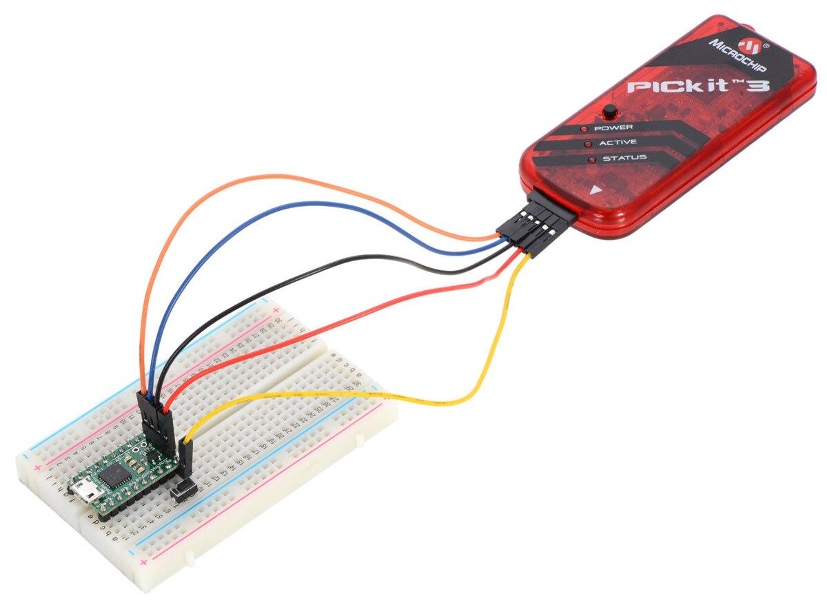 |
The P-Star 25K50 Micro connected to a PICkit 3 programmer and a reset button. |
|---|
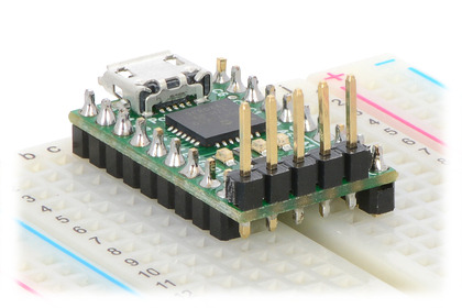
Another option for connecting a P-Star to a PICkit is to solder upwards-pointing header pins on all five programming pins, as shown below. The PICkit 3 can then be directly connected to this five-pin header, or it could be connected through a set of male-female premium jumper wires. This configuration of header pins prevents the MCLR pin from plugging directly into a breadboard, but it could still be connected via a jumper wire.
|
|
8. Compiling P-Star examples
The P-Star Examples repository contains several example programs for the P-Star that show how to use the USB interface and other parts of the P-Star. The README.md file in the repository has instructions for building the examples with the MPLAB Xpress online IDE or the MPLAB X IDE.
9. Compiling a USB application with M-Stack
The examples in Section 8 show how to use the Microchip USB stack on the P-Star. M-Stack is an alternative USB stack for PICs that we have modified to work on the P-Star.
This section explains how to compile a USB application using M-Stack, a USB device stack that is an alternative to the Microchip USB stack.
This tutorial will explain how to use MPLAB X and XC8 to compile the demo apps that come with M-Stack and run them on the P-Star 25K50 Micro. These apps can be used as a starting point for your own app. You can see what demo apps are available by looking in the M-Stack apps folder on github.
- First, install MPLAB X, XC8, and XC16. We will use MPLAB X and XC8 to compile the example code. We will not use XC16, but the MPLAB X projects we will open have configurations that use XC16 and installing it will avoid some issues when opening those projects.
- Next, download the Pololu fork of M-Stack. If you download it as a ZIP archive, be sure to extract the files from the ZIP archive before continuing.
- Run the MPLAB X IDE.
- In the “File” menu, select “Open Project…”, and navigate to
apps\hid_mouse\MPLAB.X. Select theMPLAB.Xfolder and click “Open Project”. - In the “Production” menu, set the Main Project to be the project you just opened.
- In the “Production” menu, set the project configuration to “P-Star_25K50_Micro”. This configures the project so that it will be built for the PIC18F25K50 and use the
--codeoffset 0x2000option so that it can be loaded with the P-Star’s bootloader. - If your P-Star is based on the PIC18F45K50, you should reconfigure MPLAB X to compile for the correct microcontroller. To do this, open the “File” menu and select “Project properties”. On the left-hand side of the Project Properties window, select the “P-Star_25K50_Micro” configuration. Set the Device for this configuration to the model of the PIC on your P-Star (e.g. “PIC18F45K50”). You can also rename the configuration to avoid confusion. Click OK.
- In the “Production” menu, select “Build Main Project”.
- The “Output” pane should now show the build output from MPLAB X. One of the last lines of the output should say “Loading code from” and have the full path to the HEX file produced during compilation.
- Use p-load to load this HEX file onto the P-Star using its USB bootloader, as described in Section 5.4.
- If the app runs successfully, it should connect to the computer as a standard USB mouse and you should see your mouse cursor moving back and forth horizontally. To regain normal use of your cursor, you can disconnect the P-Star from USB or put it back into bootloader mode as described in Section 5.2.
These instructions will also work for any other example app in M-Stack, except for the bootloader app.
Where to find more information
We recommend reading the README.txt file that comes with M-Stack.
For information about USB, see the USB 2.0 Specification.
For information about the USB module on the PIC, see the PIC18F25K50/PIC18F45K50 datasheet.
To write PC software to communicate with the P-Star over USB using a generic USB interface, see libusb.
10. Compiling a program with MPLAB X and MPASM
This section explains how to get started programming the P-Star in assembly using MPLAB X and XC8. MPLAB X a free integrated development (IDE) from Microchip for programming their PIC microcontrollers. MPASM is an assembler that comes with MPLAB X.
For most people, we recommend “developing P-Star apps with XC8”:Section 5.3, which allows a mixture of C and assembly code. This section is for advanced users who only want to use assembly.
MPASM supports two types of code: absolute and relocatable. These instructions will show how to write absolute code, where the location of every instruction and variable is known ahead of time. The alternative is relocatable code, which allows multiple assembly files to be combined into one program using a linker.
- Download and install the latest version of MPLAB X.
- Find “MPLAB X IDE” in your Start Menu and run it.
- From the File menu, select “New Project”.
- On the first screen of the New Project wizard, select the “Microchip Embedded” category and then select “Standalone Project”. Click “Next”.
|
- For the Device, type the name of the microcontroller on your P-Star, which is either “PIC18F25K50” or “PIC18F45K50”. Click “Next”.
|
- On the “Select Tool” screen, you can select “PICkit 3” but this choice does not matter because we will not use MPLAB X to the load the program onto the board.
- For the compiler, select MPASM.
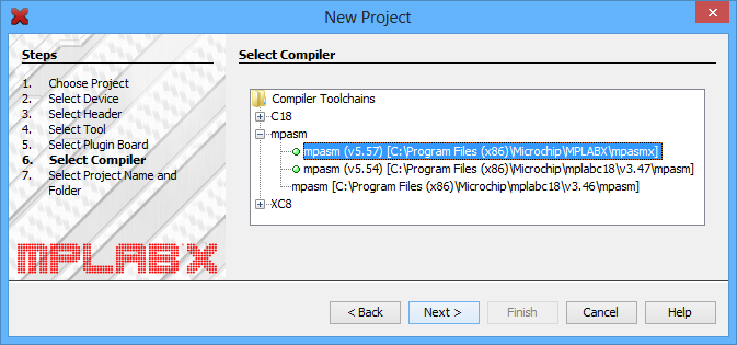 |
- For the Project Name, choose something like “p-star1”, and choose the folder you want it to be in. Click “Finish” to create the project.
|
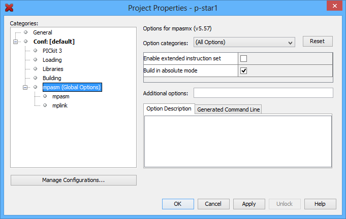
- In the “File” menu, select “Project Properties”. In the “MPASM (global options)” category, check the “Build in absolute mode” check box, then click “OK”.
 |
- Now we need to create the assembly source file. Locate the “Projects” pane. If the “Projects” pane is not visible, you can open it by opening the “Window” menu and selecting “Projects”. Left-click the “+” sign next to “Source Files” to expand it and verify that your project has no source files yet. Then right-click on “Source Files”, select “New”, and then select “pic_8b_simple.asm…”. If “pic_8b_simple.asm” is not visible in the menu, you can find it by selecting “Other…”, “Microchip Embedded”, and then “MPASM assembler”.
 |
- Choose a file name such as “main” and then click “Finish”. This should create a new file named “main.asm” and open it for editing.
- Copy and paste the following code into main.asm, replacing all the code that was there by default:
- To compile the code, open the “Run” menu and select “Build Main Project”.
- The “Output” pane should show the build output from MPLAB X. One of the last lines of the output should say “Loading code from” and have the full path to the HEX file produced during compilation.
    #include <p18f25k50.inc>

    org     0x2000
    goto    start

    org     0x2020
ledRedOn:
    bcf     TRISC, 6
    return

ledRedOff:
    bsf     TRISC, 6
    return

start:
    bcf     LATC, 6      ; Set up the red LED

    ; Enable Timer 0 as a 16-bit timer with 1:256 prescaler:
    ; since the instruction speed is 12 MHz, this overflows about
    ; every 1.4 seconds.
    movlw   b'10000111'
    movwf   T0CON

mainLoop:
    movf    TMR0L, W    ; Trigger an update of TMR0H

    ; Blink the red LED with a period of 1.4 s.
    btfss   TMR0H, 7
    rcall   ledRedOff
    btfsc   TMR0H, 7
    rcall   ledRedOn

    goto    mainLoop

    end
If your P-Star has a PIC18F45K50, the code above will work as is, but you should change it to include p18f45k50.inc instead of p18f25k50.inc.
Where to find more information
For information about the instruction set, hardware peripherals, and registers on the PIC, see the PIC18F25K50/PIC18F45K50 datasheet.
For information about MPLAB X, you can find useful resources under the “Help” menu and in the “docs” directory inside your MPLAB X installation.
For information about MPASM, see its user’s guide, which is in the “mpasmx/docs” directory inside your MPLAB X installation.
If you have questions, you can post in Microchip’s MPASM forum or the Pololu Robotics Forum.
11. Compiling a program with PICBASIC PRO
The P-Star is compatible with PICBASIC PRO, a BASIC language compiler from microEngineering Labs that runs on Microsoft Windows and targets PIC microcontrollers. This section explains how to compile a program and load it onto the P-Star using MicroCode Studio, the IDE that comes with PICBASIC PRO. PICBASIC PRO is not free, but there is a trial version that you can try for a limited number of days before deciding whether to purchase PICBASIC PRO.
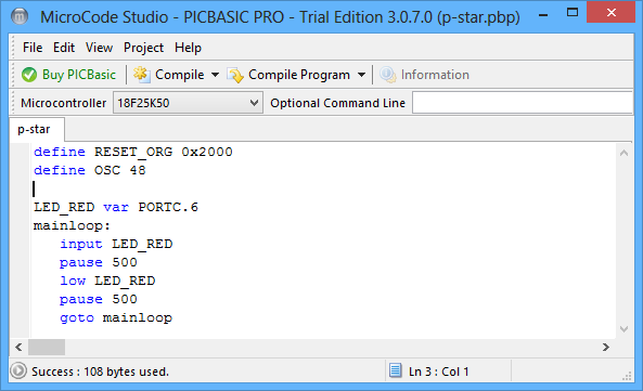 |
MicroCode Studio with a simple program for the P-Star 25K50 Micro. |
|---|
- Download and install PICBASIC PRO from the PICBASIC PRO Compiler Downloads page.
- Find “MicroCode Studio (MCSX)” in your Start Menu and run it.
- Locate the “Microcontroller” dropdown in the upper-left corner, and select the microcontroller on your P-Star, which is either “18F25K50” or “18F45K50”.
- Copy and paste this code into your program:
Define RESET_ORG 0x2000
Define OSC 48

LED_RED VAR PORTC.6
mainloop:
   Input LED_RED
   Pause 500
   Low LED_RED
   Pause 500
   Goto mainloop
- Click the “Compile” button to compile the program. If you have not saved yet, you will be prompted to choose a location to save the program. After the compilation succeeds, you will have a valid HEX file and you could load it onto the P-Star using the Pololu USB Bootloader Utility (p-load) from the command line. However, we recommend following the instructions below which explain how to integrate p-load with MicroCode Studio so you can load your program onto the P-Star without leaving the IDE.
- Locate the “Compile Program” toolbar button and open its menu by clicking the triangle to its right. If you see p-load as an option in this list, then you have probably done these steps before and can skip to step 13.
- Select “Install New Programmer…”. In the dialog that opens, select “Create a custom programmer entry” and click “Next”.
- For the “Display Name”, enter “p-load”. Click “Next”.
- For the “Programmer Filename”, enter “p-load.exe”. Click “Next”.
- Click the “Find Manually…” button and select the p-load “bin” folder. If you installed p-load in the default location, the bin folder can be found at “C:\Program Files (x86)\Pololu\USB Bootloader Utility\bin”. Click “Next”.
- For the “Parameters”, enter the following line:
--pause-on-error -w "$hex-filename$"
- Click “Finished” to finish adding the new programmer, and click “OK” to exit the parent dialog box.
- Open the menu for the “Compile Program” toolbar button again to make sure that “p-load” is checked.
- Make sure that the P-Star is in bootloader mode as described in Section 5.2. The yellow LED should be on and the green LED should be showing a double-blink pattern.
- Click the “Compile Program” button. This compiles the program and runs p-load to load it onto the P-Star.
You should briefly see a window that shows the output from p-load. If everything worked, then the P-Star’s red LED should now be blinking with a period of one second.
Related products


Home | Forum | Blog | Support | Ordering Information | Lists | Distributors | BIG Order Form | About | Contact
© 2001–2026 Pololu Corporation
