Support » Pololu RC Switch User’s Guide » 6. RC Switch with Relay »
6.1. Pinout
 |
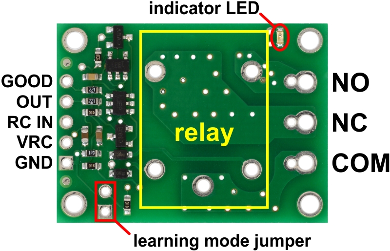
Pololu RC Switch with Relay, labeled top view. |
|---|
The Pololu RC Switch with Relay has five pins spaced 0.1″ apart that give access to its logic interface.
RC interface
The GND, VRC, and RC IN pins make up the switch’s RC interface and can be connected directly to an RC receiver or servo controller:
- The GND pin is the ground or reference voltage.
- The VRC pin is the power input.
- The RC IN pin is the RC signal input. The switch measures the width of pulses on this line and uses that to decide whether to activate or not.
Power
We generally recommend that you supply the GND and VRC pins with power from a 4- or 5-cell NiMH or NiCD battery pack. Typically, the input voltage range will be limited by the properties of the relay coil. The included Omron G5LE-14-DC5 relay requires an input voltage of at least 3.75 V to operate. At room temperature (23° C), the relay can tolerate voltages up to 8.5 V, but this limit decreases at higher temperatures. At 85° C, the relay can only tolerate voltages up to 6.5 V. You can see the Omron G5LE-14-DC5 datasheet (1MB pdf) for more information. As a whole, the switch will draw about 100 mA when the relay is on, but that current draw depends on the input voltage. The board itself can operate anywhere in the 2.5 to 16 V range, but the included Omron relay requires a more restrictive range of voltages.
Relay interface
The NO, NC, and COM pins are connected directly to the relay.
- NO stands for “normally open”. This pin is normally disconnected from the COM pin, but they become connected when the relay is active.
- NC stands for “normally connected”. The NC pin is normally connected to the COM pin through the relay, but they become disconnected when the relay is active.
- COM stands for “common”.
These pins are electrically isolated from the logic side of the board and are routed on the PCB with a minimum clearance of 60 mils (1.5 mm) from other copper and from the board edges, though manufacturing variations in the board edges can make those distances slightly lower.
In most applications, the current and voltage ratings for the module will match the ratings of the relay used. Maximum current, maximum voltage, and life expectancy are interdependent; we therefore recommend careful examination of your relay’s datasheet. If you are using the included relay, please refer to the Omron G5LE-14-DC5 datasheet (1MB pdf) for information.
Warning: The RC Switch with Relay is not designed to or certified for any particular high-voltage safety standard. Working with voltages above 30 V can be extremely dangerous and should only be attempted by qualified individuals with appropriate equipment and protective gear.
Outputs and indicator LED
The RC switch provides feedback about what state it is in via a yellow indicator LED. The LED behavior is described in Section 9. Status information is also provided by two additional outputs:
- The GOOD pin indicates the presence of a valid RC signal (10–330 Hz pulse rate, 0.5–2.5 ms pulse width).
- The OUT pin indicates whether the relay is activated (i.e. the relay coil is energized).
When high, the GOOD and OUT outputs will output a voltage approximately equal to 5 V or VRC, whichever is lower. When low, these outputs will be at 0 V (ground). These outputs have 220 Ohm resistors in series with them to protect them from short circuits.
Configuration interface
The learning mode jumper can be used to get the device into learning mode and configure it. The configuration procedure is described in Section 10.
 |
Pololu RC Switch with Relay carrier board, labeled top view. |
|---|
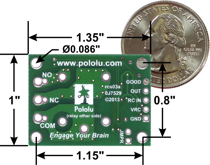 |
Pololu RC Switch with Relay, bottom view with dimensions. |
|---|
Included hardware
The Pololu RC Switch with Relay is available in two versions:
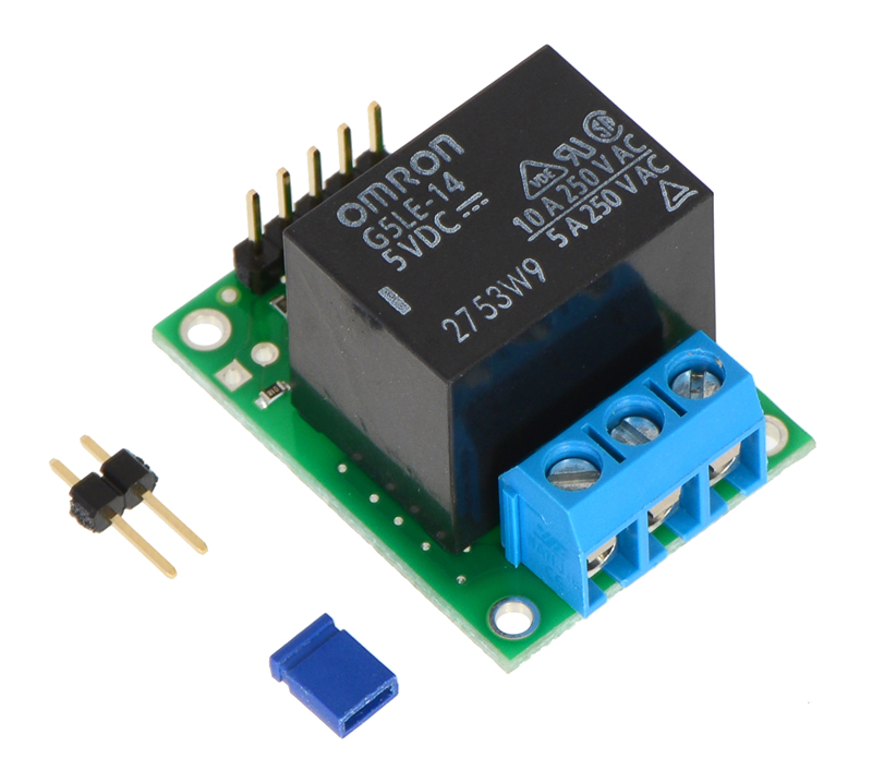
- The assembled version ships with the 5V Omron relay, header pins, and terminal block soldered in. A 1×2-pin male header and a shorting block are also included with the assembled version and can be used together as a tool when configuring the device. The assembled version can be incorporated into an existing RC system without the need for any additional soldering.
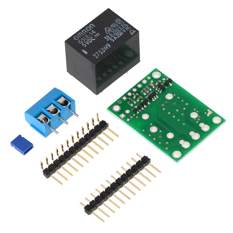
- The partial kit version gives you the flexibility to choose different connections. It includes a 5V Omron relay, 0.1″ 12-pin male header, a 0.1″ 12-pin right-angle male header, a 3-pin terminal block, and a shorting block. The headers can be broken into smaller pieces and optionally soldered to the board, or wires can be soldered directly to the board for the most compact installation.
Warning: When soldering the terminal block into the partial kit version, be sure to use the larger set of holes. If you use the smaller holes, which are intended for 0.2″ male header pins, there will not be enough space to mount the relay.
|
|
Related products


Home | Forum | Blog | Support | Ordering Information | Lists | Distributors | BIG Order Form | About | Contact
© 2001–2026 Pololu Corporation
