Support »
Sample Project: Wixel USB Joystick
View document on multiple pages.
- 1. Introduction
- 2. Materials and Tools
- 3. Construction
- 4. Loading and configuring the Joystick App
- 5. Suggested Modifications and Improvements
- 6. Conclusion and Community
1. Introduction
Modern computer systems often receive user input from USB devices like keyboards, mice, and game controllers. These input devices typically belong to the Human Interface Device (HID) class defined by the USB specification.
The Wixel is a versatile device that can be programmed to act as a standard HID device, appearing to a computer as a keyboard, a mouse, a joystick, or even a combination of multiple interfaces. We have written a Joystick App that does just that, and this tutorial shows how you can use a Wixel and the Joystick App to convert a non-USB joystick into a USB device. You will not need any knowledge of computer programming or USB for this project, although you will need soldering skills.
Even though the Wixel has wireless capabilities, we will be making a wired USB device in this tutorial.
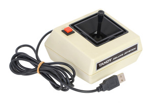
 |
Wixel programmable USB wireless module (fully assembled) with USB cable connected. |
|---|
2. Materials and Tools
Beyond the Wixel, you will need a suitable input device to convert. We used a Tandy Deluxe Joystick for this tutorial, but any device that uses pushbuttons, switches, and/or potentiometers for input will probably work.
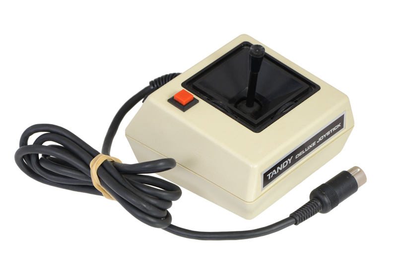 |
The Tandy Deluxe Joystick in its original form. |
|---|
The tools and supplies you require will probably depend on your particular situation, but might include:
- Screwdrivers
- Soldering iron and solder
- Diagonal cutter
- Wire stripper
- Some wire for making connections to the Wixel
- Double-sided foam tape or hot glue gun
- USB cable, A to Mini-B
Many of the tools are available in the Tools section of the Pololu web site.
3. Construction
To begin converting an input device with a Wixel, you first need to make the appropriate electrical connections and integrate the Wixel into the device physically. This section of the guide demonstrates the construction process with the Tandy joystick we converted.
Step 1: Disassemble the joystick and look at its wiring.
First, you need to open up your input device to allow access to the pins on its buttons and potentiometers.
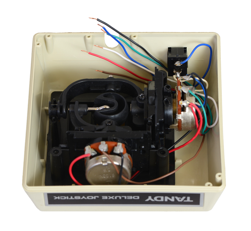
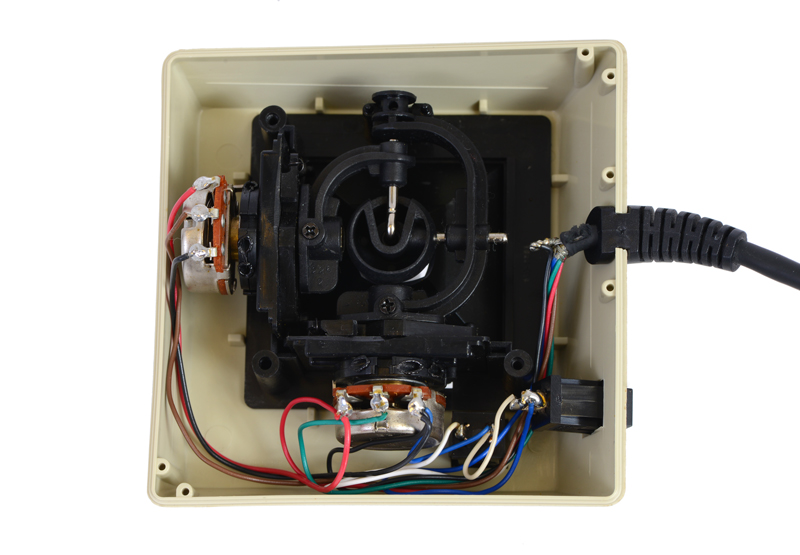 |
Inside the unmodified Tandy joystick. |
|---|
In the case of this Tandy joystick, we could see that the wires from the components went directly into the joystick’s original cable, so we were able reuse those wires to connect the components to the Wixel.
In some other input devices, such as certain gamepads, the components might instead be connected to a microcontroller or other logic inside the device. To convert such a device, you might need to make new wire connections between the components and the Wixel, and you might need to cut existing connections to ensure the original circuits don’t interfere with the Wixel’s inputs.
Step 2: Determine how to wire the buttons and potentiometers to the Wixel.
The Wixel’s Joystick App supports two kinds of inputs: digital signals can be used to represent joystick buttons, and analog voltages can be used to represent joystick axis positions. Each physical button and potentiometer in the device needs to be wired to the Wixel appropriately so that its state can be read by the Wixel.
Button or switch
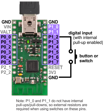 |
Diagram for connecting a button or switch to the Wixel for use with the Joystick App. |
|---|
Pushbuttons and switches can be connected to any of the Wixel’s digital I/O pins on Port 0 (P0_0 through P0_5) or Port 1 (P1_0 through P1_7).
The picture on the right shows the easiest way to do this: the button or switch should be connected between the selected pin and GND (0 V), and the internal pull-up resistor on the pin should be enabled. (Pull-up settings can be changed when the Joystick App is loaded onto the Wixel, as discussed later in in Section 4.) In this configuration, the input will be pulled high (3.3 V) when the switch is open, and it will fall to 0 V when the switch is closed.
The Joystick App allows you to change how each input maps to a joystick function (for example, you could designate P1_6 to represent Button 0 and P1_3 to represent Button 1), so you have a choice of which input pin to use for each button or switch. However, you should be aware of limitations when using certain pins:
- Using any of the Port 0 pins as a digital input (button) prevents it from being used as an analog input (axis).
- Pins P1_0 and P1_1 do not have internal pull-ups/pull-downs, so you will need to connect an external pull-up or pull-down resistor to use either of these pins with a button or switch.
Our Tandy joystick has two buttons, and we connected them to pins P1_2 and P1_3.
Potentiometer
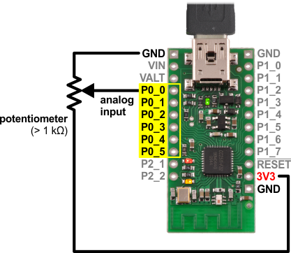 |
Diagram for connecting a potentiometer to the Wixel for use with the Joystick App. |
|---|
Potentiometers can be connected to any of the Wixel’s analog input pins on Port 0 (P0_0 through P0_5).
The picture on the right shows the correct way to connect a potentiometer to an analog input: the end terminals of the potentiometer should be connected between 3V3 (the Wixel’s 3.3 V output) and GND (0 V), and the wiper terminal should be connected to the selected pin. This way, the voltage on the wiper seen by the analog input will change from 0 V at one end of the potentiometer’s range to 3.3 V at the other end.
The potentiometer should have a resistance of at least 1 kilo-ohm so that it does not draw too much current from the 3V3 line. The Tandy joystick contains two 100k potentiometers, one for each axis; we connected them to P0_0 and P0_1.
Caution: The Wixel’s I/O lines are not 5 V tolerant, so you must not connect voltages over 3.3 V to these pins.
Step 3: Solder the button and potentiometer connections to the Wixel.
We prepared the existing wires in our joystick by cutting them and stripping their ends. As discussed in Step 1, we were able to simply connect the wires in this joystick directly to the Wixel, but a different device might require more modification. If you are unsure about the connections you need to make, it might be a good idea to try making temporary connections to the Wixel (e.g. with test leads) and skip to loading the Joystick App onto the Wixel to see if your converted device works as you expect.
 |
Wires cut and stripped inside the joystick. |
|---|
For maximum compactness, we soldered the wires directly to the pins we have chosen on the Wixel.
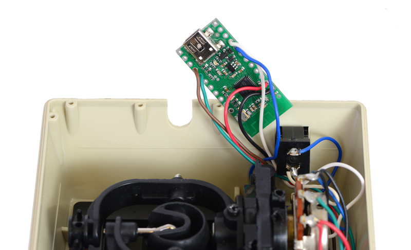 |
Joystick wires soldered to a Wixel. |
|---|
Step 4: Connect a USB cable and mount the Wixel inside the joystick.
Since you might have to reload the app a few times to change the configuration settings, you will need access to the Wixel in order to put it into bootloader mode. This means it is a good idea to mount the Wixel in a way that still allows you to connect P2_2 to 3V3 and to leave the housing of the device open for now.
Once a USB cable is plugged into the Wixel and it is secured, the construction of the device will be complete, and you will be ready to load and configure the Joystick App on the Wixel. We used double-sided foam tape to attach the Wixel to a convenient spot inside the joystick’s housing.
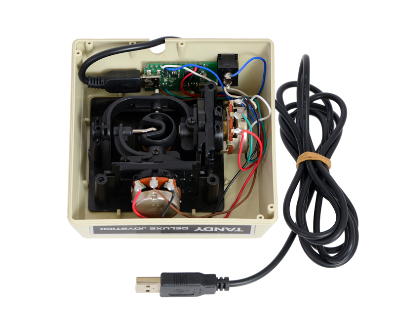 |
Joystick with Wixel mounted inside and USB cable attached. |
|---|
4. Loading and configuring the Joystick App
Once your input device has been properly wired to the Wixel, you can proceed to load the Joystick App onto the Wixel and configure it to represent the device’s functions correctly.
Step 1: If necessary, install drivers and software for the Wixel.
See Section 3 of the Wixel user’s guide for instructions to install the Wixel Configuration Utility and any necessary drivers on your computer.
Step 2: Download the Joystick App.
The Joystick App can be downloaded from Section 9.g of the Wixel User’s Guide, and you can read detailed information about the app there.
Step 3: Open the Joystick App in the Wixel Configuration Utility.
Do not write the app to the Wixel yet. (Section 4 of the Wixel user’s guide explains how to use the Wixel Configuration Utility.)
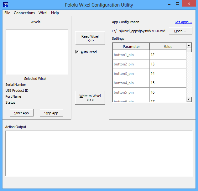 |
The Joystick App opened in the Wixel Configuration Utility. |
|---|
Step 4: Configure the app parameters.
If you wired your device the same way we did in Section 3, you might not need to change any parameters from their default values at all. In case you do need to change some, though, here is a list of the parameters and what they do:
- The buttonB_pin parameters determine which digital input pin on the Wixel corresponds with each logical joystick button. For example, if you want a button connected to pin 1_5 to be Button 3, you should set button3_pin to 15.
- The buttonB_invert parameters determine whether a logic high or logic low voltage indicates a button press for each pin. If you connected your buttons according to the diagram in Section 3, you should set these parameters to 1 to specify that the inputs are inverted (a logic low indicates a button press), since each pin will be connected to ground when the button is pressed and pulled high when the button is released.
- The axis_channel parameters determine which analog input represents each joystick axis. For example, if you want a potentiometer connected on P0_2 (ADC channel 2) to measure Y-axis rotation, you should set Y_channel to 2.
- The axis_invert parameters determine whether to flip the reported position for each axis with respect to the voltage on the corresponding analog input. If you find that an axis of your joystick is reversed, you can toggle the inversion parameter for that axis to correct it.
- The PM_N_pull_enable parameters determine whether the internal pull-up or pull-down resistor on the corresponding pin, and the portM_pull_type parameters determine whether each port is pulled up or down. (The pull-ups/pull-downs can be enabled or disabled for each individual pin, but every pin on the same port must be pulled in the same direction.) To match the diagram in Section 3, you should set the pull_enable parameter to 1 for each pin that has a button connected, and you should set the pull_type parameters to 1 to pull the pins up. Make sure the pull_enable parameter is set to 0 for pins being used as analog inputs so that the pull-ups do not influence the analog readings.)
The app documentation also describes the parameters in detail.
Step 5: Connect the Wixel to your computer and write the app to it.
Once you have successfully written the Joystick App to the Wixel, it should show up to your computer as a Human Interface Device. In addition to appearing as a joystick, the Wixel will also show up as a keyboard and a mouse, but the Joystick App does not use those interfaces.
If you are using Windows, you should see a new entry called “HID-compliant game controller” in your Device Manager in the “Human Interface Devices” section. On Linux, you should see a new device node with a name like /dev/input/js0 that represents the joystick.
Step 6: Test the joystick.
To test the joystick functions on Windows, you can use the Game Controllers applet in the Control Panel, where you should see a “Wixel Joystick” entry. Selecting this entry and clicking the Properties button will display a dialog that shows the state of the joystick’s axes and buttons. On Linux, you can try using the programs jstest or jstest-gtk.
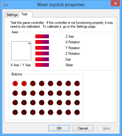 |
The converted Tandy joystick being tested with its properties dialog in Windows. The stick has been moved forward and right, and both buttons are being pressed. |
|---|
If your input device is being read by your computer and behaving correctly, congratulations! You can now finish reassembling it and start using it.
 |
This converted Tandy Deluxe Joystick is now usable as a USB Human Interface Device. |
|---|
Changing parameters and reloading the app
If your device is not behaving the way you expect, you probably need to adjust the app parameters. To do this, you need to manually put the Wixel into bootloader mode, since the Wixel Configuration Utility does not detect Wixels with USB HID interfaces.
- Connect P2_2 to 3V3 on the Wixel using a wire. The Joystick App monitors the voltage on P2_2 and starts the bootloader if it goes high. The Wixel should now appear in the Wixel Configuration Utility.
- Select the Wixel in the configuration utility. If the “Auto Read” checkbox is checked, the Wixel’s current settings will be retrieved and displayed in the configuration utility; otherwise, you can click the “Read Wixel” button to do this.
- Check the parameter values and make any necessary changes.
- Write the app to the Wixel and test it again.
5. Suggested Modifications and Improvements
Here are some ideas for additional things to try with the Wixel and Joystick App:
- The Joystick App only supports using digital and analog voltages directly as input, but by modifying the source code, you could add support for encoders and other types of sensors.
- In addition to buttons and analog axes, the HID specification allows for many other types of controls to be represented, such as hat switches. You could modify the Wixel’s usb_hid library to add support for features like these; see the Wixel SDK Documentation for more information.
- With a pair of Wixels and some custom programming, you could build a wireless controller: one Wixel could read the inputs and transmit information about their states wirelessly, and the other Wixel could receive the information and pass it to a computer through an HID interface.
- Instead of converting an existing input device, you could make a custom input device from individual components. Building an arcade machine control panel from scratch? Use a Wixel to interface it to a computer!
6. Conclusion and Community
With the Wixel’s ability to act as a Human Interface Device, it can be used as a USB interface between a computer and a physical input device. The Joystick App makes it easy to configure the Wixel for use in such an application.
Did you build a USB input device with the Wixel and its Joystick App? Please join us on our robotics forum to ask questions, give feedback, or share your projects. We would love to hear about your experiences, and we would be delighted to see any improvements or alterations you make!
Related products


Home | Forum | Blog | Support | Ordering Information | Lists | Distributors | BIG Order Form | About | Contact
© 2001–2026 Pololu Corporation
