Support » Pololu Wixel User’s Guide » 9. Wixel Apps »
9.g. Joystick App
Overview
 |
This converted Tandy Deluxe Joystick is now usable as a USB Human Interface Device. |
|---|
This app allows a Wixel connected to a computer to be used as a joystick. Readings from the Wixel’s analog and digital input pins can represent up to six analog axes and 16 digital buttons or switches. The Wixel appears to the computer as a standard USB Human Interface Device (HID); after the Wixel has been configured, no driver installation is necessary to use the joystick. With a Wixel running the Joystick App, you can easily build a custom USB input device or convert an existing device into a USB peripheral, as this sample project shows.
Default Pinout
| Wixel pin | Input type | Joystick function |
|---|---|---|
| P0_0 | Analog | X axis |
| P0_1 | Y axis | |
| P0_2 | Z axis | |
| P0_3 | Rx axis | |
| P0_4 | Ry axis | |
| P0_5 | Rz axis | |
| P1_2 | Digital | Button 1 |
| P1_3 | Button 2 | |
| P1_4 | Button 3 | |
| P1_5 | Button 4 | |
| P1_6 | Button 5 | |
| P1_7 | Button 6 |
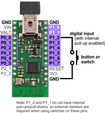
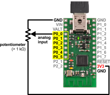
Connecting Buttons and Potentiometers
The diagrams below show examples of how buttons, switches, and potentiometers can be connected to the Wixel for use with the Joystick App. For a more comprehensive tutorial on wiring these components to build a USB input device with a Wixel, see our USB Wixel Joystick sample project.
|
|
Wixel Configuration
Download the Joystick App (v1.0) (33k wxl). Open it with the Wixel Configuration Utility, set any parameters you want to change from the default values, and then write the app to a Wixel. (See Section 4 for more information on how this is done.) The Wixel should now appear to your computer as a Human Interface Device.
If you are using Windows, there should be a new entry called “HID-compliant game controller” in your Device Manager in the “Human Interface Devices” section. The Wixel will also show up as a keyboard and a mouse, but it does not use those interfaces. To test the joystick functions, you can use the Game Controllers applet in the Control Panel, where you should see a “Wixel Joystick” entry. Selecting this entry and clicking the Properties button will display a dialog that shows the state of the joystick’s axes and buttons.
On Linux, the joystick should be represented by a new device node with a name like /dev/input/js0. You can test the joystick with a program such as jstest or jstest-gtk.
The Wixel Configuration Utility does not detect Wixels with USB HID interfaces. Therefore, if you need to reconfigure your Wixel, you will need to manually get it into bootloader mode (set pin P2_2 high and reset – although this app monitors P2_2 all the time and enters the bootloader if it goes high, so the reset is not strictly necessary).
This app’s parameters (detailed below) are used to configure how the Wixel’s inputs map to joystick functions. By default, the six analog inputs P0_0 through P0_5 are mapped to six analog joystick axes, and the six digital inputs P1_2 through P1_7 are mapped to six joystick buttons. Pull-ups are enabled for the buttons, which are configured as inverted inputs (so the Wixel interprets a logic low as a button press). If you don’t need all of the joystick axes, some or all of them can be disabled and the analog pins can be used as digital inputs for additional buttons instead.
Parameters
- buttonB_pin: The digital input pin that represents a joystick button; for example, a value of 12 selects the P1_2 pin. A value of -1 disables the button.
- buttonB_invert: Set to 0 for a non-inverted input: a logic high on the pin indicates a button press. Set to 1 for an inverted input: a logic low on the pin indicates a button press. The default is 1 (inverted).
- axis_channel: The analog input (ADC channel) that represents a joystick axis. A value of -1 disables the axis.
- axis_invert: Set to 0 for a non-inverted axis: the axis position is proportional to the input voltage. Set to 1 for an inverted axis: the axis position is inversely proportional to the input voltage. The default is 0 (non-inverted).
- PM_N_pull_enable: Enables (1) or disables (0) the internal pull-up or pull-down resistor on the corresponding pin. (Note that P1_0 and P1_1 do not have pull-ups/pull-downs.) The direction the pin is pulled is determined by the portM_pull_type parameter for Port M. The default is 0 (disabled) for Port 0, to avoid interfering with analog readings, and 1 (enabled) for Port 1.
- portM_pull_type: Determines whether a pin on Port M is pulled down (0) or up (1) when the pin’s PM_N_pull_enable parameter is set. The default is 1 (high).
Versions
- Joystick App v1.0 (33k wxl), released 2013-08-12: Initial release.


Home | Forum | Blog | Support | Ordering Information | Lists | Distributors | BIG Order Form | About | Contact
© 2001–2026 Pololu Corporation
