3. Hardware Construction

<table class="picture_with_caption right"><tr><td><img alt="" class="" data-gallery-pictures="[{&quot;id&quot;:&quot;0J319&quot;,&quot;caption&quot;:&quot;\u003cp\u003eLEGO motor.\u003c/p\u003e&quot;,&quot;url_tiny&quot;:&quot;https://a.pololu-files.com/picture/0J319.98x98.jpg?b9fd12e4e8d86bc9c6a8ca3968329502&quot;,&quot;url_medium&quot;:&quot;https://a.pololu-files.com/picture/0J319.600x480.jpg?b9fd12e4e8d86bc9c6a8ca3968329502&quot;,&quot;url_full&quot;:&quot;https://a.pololu-files.com/picture/0J319.1200.jpg?b9fd12e4e8d86bc9c6a8ca3968329502&quot;,&quot;longest_side&quot;:300}]" data-picture-id="0J319" data-picture-longest_side="300" src="https://a.pololu-files.com/picture/0J319.300.jpg?b9fd12e4e8d86bc9c6a8ca3968329502" /></td><p></tr></table></p> <p>
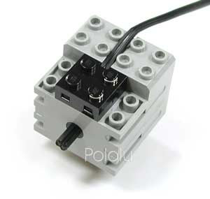
Although we do not wish to dwell on the mechanical aspects of this project, the LEGO motor is worth mentioning. Within the compact housing are both a small motor and a very efficient gearbox. The motor is fairly expensive, but you&#8217;ll immediately appreciate how much more quietly it runs than cheaper gearboxes. Because the motor draws only approximatly 100 mA, it is perfect for use with our micro motor controller. <br clear="all"/></p> <table class="picture_with_caption right"><tr><td><img alt="" class="" data-gallery-pictures="[{&quot;id&quot;:&quot;0J320&quot;,&quot;caption&quot;:&quot;\u003cp\u003eLEGO motor connector.\u003c/p\u003e&quot;,&quot;url_tiny&quot;:&quot;https://a.pololu-files.com/picture/0J320.98x98.jpg?6f44e21644befb46e33baff1558a7777&quot;,&quot;url_medium&quot;:&quot;https://a.pololu-files.com/picture/0J320.600x480.jpg?6f44e21644befb46e33baff1558a7777&quot;,&quot;url_full&quot;:&quot;https://a.pololu-files.com/picture/0J320.1200.jpg?6f44e21644befb46e33baff1558a7777&quot;,&quot;longest_side&quot;:300}]" data-picture-id="0J320" data-picture-longest_side="300" src="https://a.pololu-files.com/picture/0J320.300.jpg?6f44e21644befb46e33baff1558a7777" /></td><p></tr></table></p> <p>
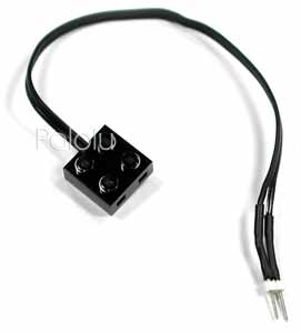
To use the LEGO motors in you own project, you need to get leads that you can connect to your own electronics. One possibility is to cut a regular LEGO cable in half and solder on male header pins onto the cut wires. This will give you the two necessary connectors at the expense of one LEGO cable. <br clear="all"/></p> <table class="picture_with_caption right"><tr><td><img alt="" class="" data-gallery-pictures="[{&quot;id&quot;:&quot;0J321&quot;,&quot;caption&quot;:&quot;\u003cp\u003eCircuit for the Basic LEGO robot.\u003c/p\u003e&quot;,&quot;url_tiny&quot;:&quot;https://a.pololu-files.com/picture/0J321.98x98.jpg?ec2b4f7ad960de53a993e47b728f49dc&quot;,&quot;url_medium&quot;:&quot;https://a.pololu-files.com/picture/0J321.600x480.jpg?ec2b4f7ad960de53a993e47b728f49dc&quot;,&quot;url_full&quot;:&quot;https://a.pololu-files.com/picture/0J321.1200.jpg?ec2b4f7ad960de53a993e47b728f49dc&quot;,&quot;longest_side&quot;:300}]" data-picture-id="0J321" data-picture-longest_side="300" src="https://a.pololu-files.com/picture/0J321.300.jpg?ec2b4f7ad960de53a993e47b728f49dc" /></td><p></tr></table></p> <p>
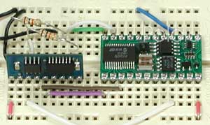
We built the electronics on a small solderless breadboard. As you can see from the close-up picture to the right, there isn&#8217;t much to the circuit. The only components other than the BASIC Stamp II and the motor controller are the two pull-up resistors for the bumper switches. The schematic diagram for this circuit is shown below. <br clear="all"/></p> <table class="picture_with_caption right wide"><tr><td><img alt="" class="wide" data-gallery-pictures="[{&quot;id&quot;:&quot;0J322&quot;,&quot;caption&quot;:&quot;\u003cp\u003eSchematic for the Basic LEGO robot.\u003c/p\u003e&quot;,&quot;url_tiny&quot;:&quot;https://a.pololu-files.com/picture/0J322.98x98.jpg?0d0414854e2355bdba9361590be89f48&quot;,&quot;url_medium&quot;:&quot;https://a.pololu-files.com/picture/0J322.600x480.jpg?0d0414854e2355bdba9361590be89f48&quot;,&quot;url_full&quot;:&quot;https://a.pololu-files.com/picture/0J322.1200.gif?0d0414854e2355bdba9361590be89f48&quot;,&quot;longest_side&quot;:600}]" data-picture-id="0J322" data-picture-longest_side="600" src="https://a.pololu-files.com/picture/0J322.600.gif?0d0414854e2355bdba9361590be89f48" /></td><p></tr></table></p> <p>Using the BASIC Stamp II is very convenient because all of its I/O lines are interchangeable; the only reason we used the particular pins indicated in the schematic is because it made the wiring convenient. The Stamp&#8217;s on-board voltage regulator allows it to run straight off of a 9-volt battery, and the LEGO motors are designed to run at 9V as well. The Stamp&#8217;s regulated 5V output is used for the motor controller&#8217;s logic power supply. The diagram does not show the Stamp&#8217;s 12 I/O lines available for expansion. <br clear="all"/></p>

Related Products

Pololu Micro Dual Serial Motor Controller (No Manual)
Log In
Pololu Robotics & Electronics
Shopping cart
(702) 262-6648
Same-day shipping, worldwide
Menu
Shop Blog Forum Support
My account Comments or questions? About Pololu Contact Ordering information Distributors