Support » Pololu 3pi Robot User’s Guide » 5. How Your 3pi Works »
5.b. Power management
Battery voltage drops as the batteries are used up, but many electrical components require a specific voltage. A special kind of component called a voltage regulator helps out by converting the battery voltage to a constant, specified voltage. For a long time, 5 V has been the most common regulated voltage used in digital electronics; this is also called TTL level. The microcontroller and most of the circuitry in the 3pi operate at 5 V, so voltage regulation is essential. There are two basic types of voltage regulators:
- Linear regulators use a simple feedback circuit to vary how much energy is passed through and how much is discarded. The regulator produces a lower output voltage by dumping unneeded energy. This wasteful, inefficient approach makes linear regulators poor choices for applications that have a large difference between the input and output voltages, or for applications that require a lot of current. For example, 15 V batteries regulated down to 5 V with a linear regulator will lose two-thirds of their energy in the linear regulator. This energy becomes heat, so linear regulators often need large heat sinks, and they generally don’t work well with high-power applications.
- Switching regulators turn power on and off at a high frequency, filtering the output to produce a stable supply at the desired voltage. By carefully redirecting the flow of electricity, switching regulators can be much more efficient than linear regulators, especially for high-current applications and large changes in voltage. Also, switching regulators can convert low voltages into higher voltages! A key component of a switching regulator is the inductor, which stores energy and smooths out current; on the 3pi, the inductor is the gray block near the ball caster labeled “100”. A desktop computer power supply also uses switching regulators: peek through the vent in the back of your computer and look for a donut-shaped piece with a coil of thick copper wire wrapped around it – that’s the inductor.
The power management subsystem built into the 3pi is shown in this block diagram:
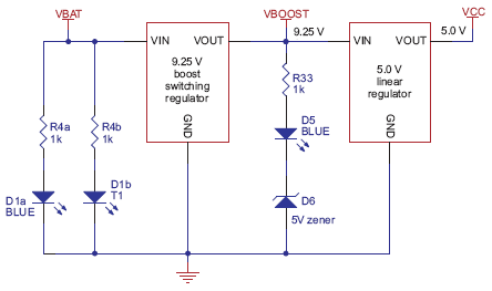 |
The voltage of 4 x AAA cells can vary between 3.5 – 5.5 V (and even to 6 V if alkalines are used). This means it’s not possible simply to regulate the voltage up or down to get 5 V. Instead, in the 3pi, a switching regulator first boosts the battery voltage up to 9.25 V (Vboost), and a linear regulator regulates Vboost back down to 5 V (VCC). Vboost powers the motors and the IR LEDs in the line sensors, while VCC is used for the microcontroller and all digital signals.
Using Vboost for the motors and sensors gives the 3pi three unique performance advantages over typical robots, which use battery power directly:
- First, a higher voltage means more power for the motors, without requiring more current and a larger motor driver.
- Second, since the voltage is regulated, the motors will run the same speed as the batteries drop from 5.5 down to 3.5 V. You can take advantage of this when programming your 3pi, for example by calibrating a 90° turn based on the amount of time that it takes.
- Third, at 9.25 V, all five of the IR LEDs can be powered in series so that they consume the lowest possible amount of power. (Note that you can switch the LEDs on and off to save even more power.)
One other interesting thing about this power system is that instead of gradually running out of power like most robots, the 3pi will operate at maximum performance until it suddenly shuts off. This can take you by surprise, so you might want your 3pi to monitor its battery voltage.
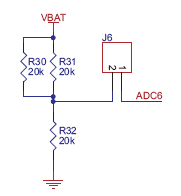 |
A simple circuit for monitoring battery voltage is built in to the 3pi. Three resistors, shown in the circuit at right, comprise a voltage divider that outputs a voltage equal to two-thirds of the battery voltage, which will always be safely below the main microcontroller’s maximum analog input voltage of 5 V. For example, at a battery voltage of 4.8 V, the battery voltage monitor port ADC6 will be at a level of 3.2 V. Using 10-bit analog-to-digital conversion, where 5 V is read as a value of 1023, 3.2 V is read as a value of 655. To convert it back to the actual battery voltage, multiply this number by 5000 mV×3/2 and divide by 1023. This is handled conveniently by the read_battery_millivolts_3pi() function (provided in the Pololu AVR Library; see Section 6 for more information), which averages ten samples and returns the battery voltage in mV:
unsigned int read_battery_millivolts_3pi()
{
	return readAverage(6,10)*5000L*3/2/1023;
}


Home | Forum | Blog | Support | Ordering Information | Lists | Distributors | BIG Order Form | About | Contact
© 2001–2026 Pololu Corporation
