Support »
Understanding Destructive LC Voltage Spikes
View document on multiple pages.
You can also view this document as a printable PDF.
- 1. Introduction
- 2. Test Setup
- 3. Initial Results
- 4. Switch Bouncing
- 5. Limiting the Magnitude of the LC Spikes
- 6. Conclusion
1. Introduction
Powering up can be one of the most dangerous events an electrical system endures: current rushes in as the circuit passes through voltages that are outside of the normal operating range and as different sub-circuits begin functioning sooner than others. Those without much electronics experience might imagine an instantaneous change in voltage or at least a gradual, monotonic rise at the power node:
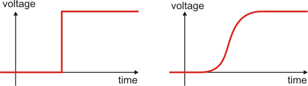 |
Ideal power-up voltage transitions. |
|---|
This might not be the case, however, especially as the circuits get more complex and the connection to power is initially intermittent, as in the case of a bouncing switch. In this article, we explore the potentially destructive voltage spikes that result from the seemingly innocuous act of applying power to a circuit with a low equivalent series resistance (ESR) capacitor across its power input.
As with many unexpected problems that we encounter in electronics, the causes of the destructive spikes we are exploring here are the non-negligible parasitic elements of the components we try to idealize. The power supply and power leads can have a relatively large inductance (L) that causes a large electromagnetic energy buildup when charging a capacitor (C). That energy is there in the magnetic field around the wires even after the capacitor voltage has reached the power supply voltage, and the collapsing magnetic field continues delivering current into the capacitor, causing its voltage to continue rising. That voltage can rise to several times the power supply voltage before the magnetic field is exhausted, which then causes the current to flow in the other direction as the capacitor discharges back into the power supply. This charging and discharging of the capacitor can happen a few times before the system stabilizes, and the frequency of the oscillations is determined by the inductance and capacitance (L and C).
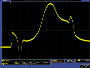
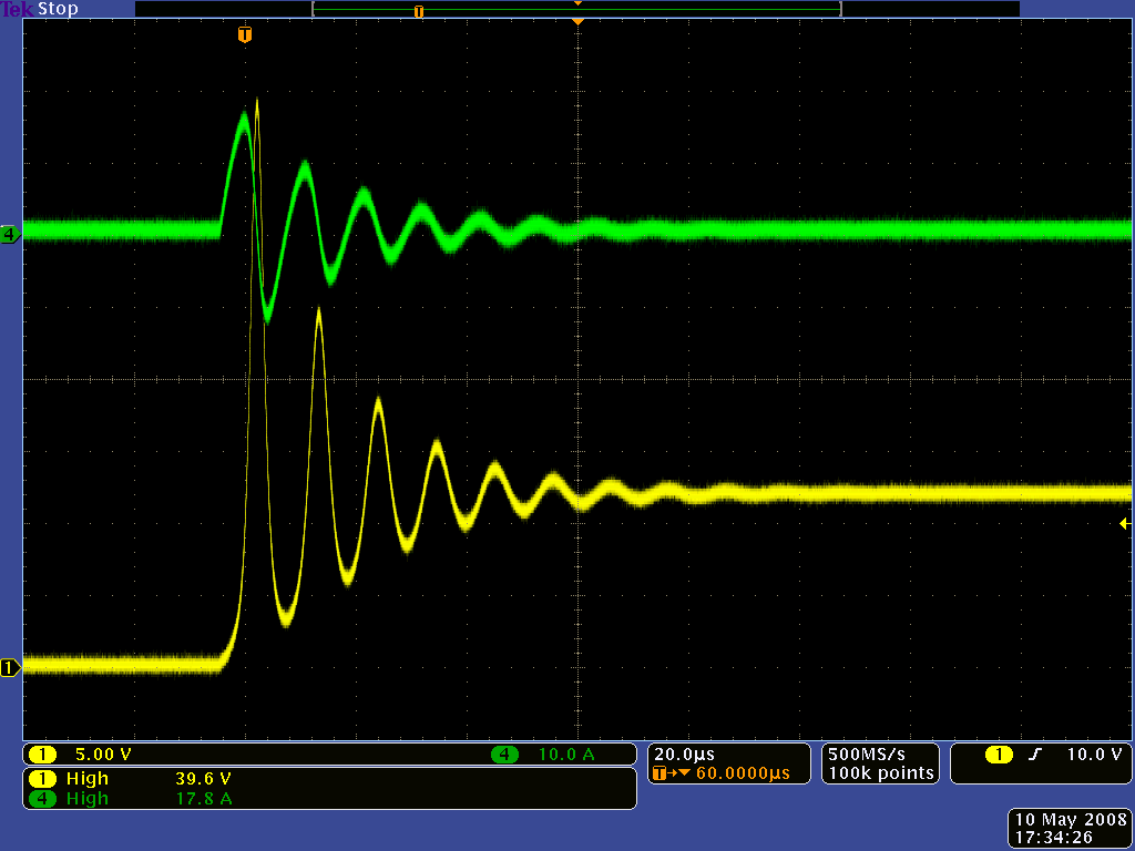 |
Oscilloscope capture showing LC spike voltage (yellow) and current (green). |
|---|
Capacitors (and wires) have a prominent parasitic feature of their own, known as the equivalent series resistance (ESR). On older capacitors, that resistance tended to be high enough to dampen the LC oscillation to the point that any spikes were negligible or even non-existent. However, newer, increasingly common ceramic capacitors have extremely low ESRs that are generally a benefit but do very little to dampen LC oscillations.
These LC-induced voltage spikes and oscillations might last for only a few milliseconds, so they’re not something you would even notice if you weren’t looking for them. However, the spikes can last long enough to destroy your electronics, so it’s definitely worth being aware of. The problem can be exacerbated by mechanical switch bouncing, which can introduce a new set of spikes with each bounce of the contacts. We hope that the oscilloscope screen shots we provide here will help illustrate this phenomenon to make it easier to understand and remember, and we suggest a few techniques for limiting the problem.
2. Test Setup
The circuit for this test consists of just three main components: a power supply, a switch, and a capacitor. We observe the voltage across the capacitor with an oscilloscope to see the start-up transients to which a circuit, represented by a load resistor, would be exposed if it were powered this way. A schematic diagram of the test circuit is shown below:
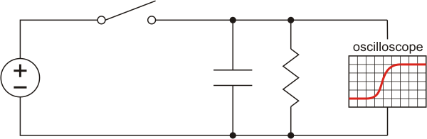 |
Schematic diagram for using an oscilloscope to measure the voltage across a capacitor after a switch is closed. |
|---|
The capacitor we used is a 10 uF (nominal; we measured it to be approximately 9 uF) multi-layer ceramic capacitor (MLCC) in a 1206 surface-mount package, which we soldered to a 2-pin male header to allow for easy breadboard use:
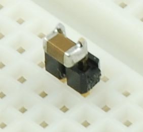 |
Ceramic capacitor soldered to 2-pin male header for breadboard use. |
|---|
The capacitor selection is important because other types of capacitors, such as electrolytic capacitors, have much higher equivalent series resistance (ESR), which dampens the spikes we are exploring. Low ESR is often a good thing, and the small size of ceramic capacitors makes them very common in small, mass-produced electronics products.
With a representative capacitor selected, we tested a typical setup with a bench power supply and power clips:
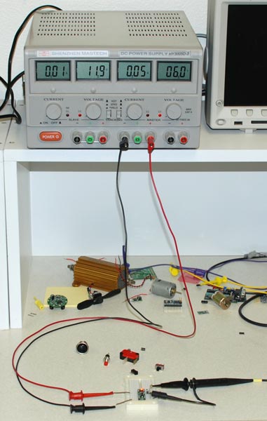 |
LC spike test setup showing bench power supply with 36" power leads. |
|---|
We conducted our tests both with mechanical switches and with the Pololu pushbutton power switch, and we later replaced the power supply with a battery and shorter leads.
3. Initial Results
We first tested the system using the bench power supply and a small slide switch:
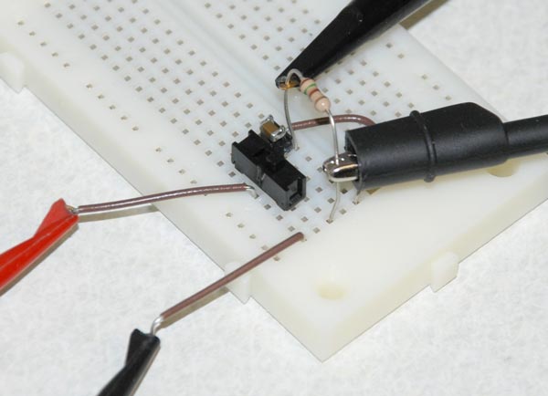 |
LC spike test setup with slide switch. |
|---|
The power supply was set to 12 V. The test clips are 20 AWG and 36" long, which are typical of what might be used in most electronics prototyping benches.
We repeatedly flipped the switch until we captured a bounce-free transition (see the next section for more on switch bouncing):
|
Oscilloscope capture showing LC spike voltage (yellow) and current (green). |
|---|
There are several noteworthy features to the above traces. Most striking is the magnitude of the first spike, which at almost 40 V is more than three times the 12 V we were attempting to apply to the circuit. We also see that there are four peaks above 15 V. The potentially destructive implications of the LC transients are clear: 12 V might seem like a safe voltage to apply to a device with a maximum voltage rating of 15 V, but the casual application of the 12 V repeatedly subjects the device to voltages outside the allowable range.
We also see that the frequency of the oscillations is just under 100 kHz, which with a capacitance of approximately 9 uF indicates that the wire inductance is a few hundred nH, which is consistent with what we would expect for the 36" leads.
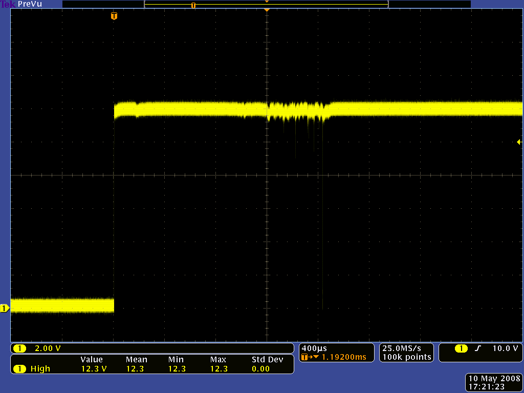
4. Switch Bouncing
Switch bouncing is another real-world problem that happens too quickly for human perception but which can doom an electronics project. When a switch is toggled, contacts have to physically move from one position to another. As the components of the switch settle into their new position, they mechanically bounce, causing the underlying circuit to be opened and closed several times. For embedded systems designers, the most common exposure to the problem is with user interface switches, in which proper care must be taken to correctly count the number of times a user presses and releases a switch.
|
|
|

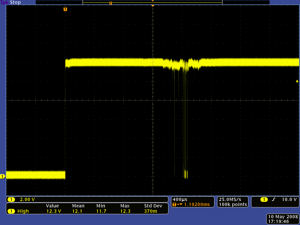
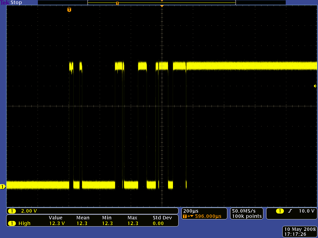
In our power switch and LC spike context, however, each additional bounce of the switch contacts can unleash a fresh set of spikes, increasing the likelihood of destroying the circuit we’re turning on. The problem usually gets worse with physically larger switches that are necessary for higher-power applications since the larger switches tend to bounce for a longer time.
|
|
|

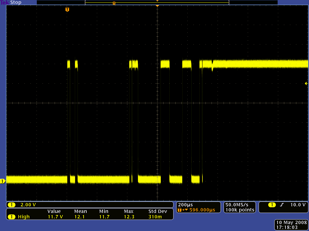
To isolate the switch bouncing effects from the LC effects, the switch bouncing screen shots above were taken without a capacitor. Once we put the capacitor back into the circuit, we can see the potentially devastating combined effect of the bouncing and the LC spikes:
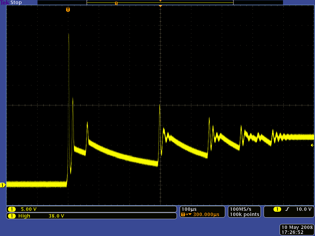 |
Oscilloscope capture of the LC voltage spikes caused by a large bouncing mechanical switch. |
|---|
The results can be even worse when a switch isn’t used at all and power is instead applied by touching a wire to a circuit or by plugging in connectors.
5. Limiting the Magnitude of the LC Spikes
There are several ways to limit the magnitude of the initial LC transients we’ve seen so far:
- Limit lead inductance
- Add resistance to the LC circuit
- Add a large, high-ESR capacitor across (in parallel with) the low ESR capacitor
Limiting Inductance
Reducing lead inductance is an obvious way to mitigate the problem caused by lead inductance. The primary way to reduce the inductance is to use shorter, thicker wires. This might not always be practical, but limiting LC transients is just one of several good reasons for avoiding excessively long wires in your designs (others include limiting resistance and reducing noise generation or susceptibility).
With the same power switch used earlier but with a battery and shorter leads we see the result is slightly improved:
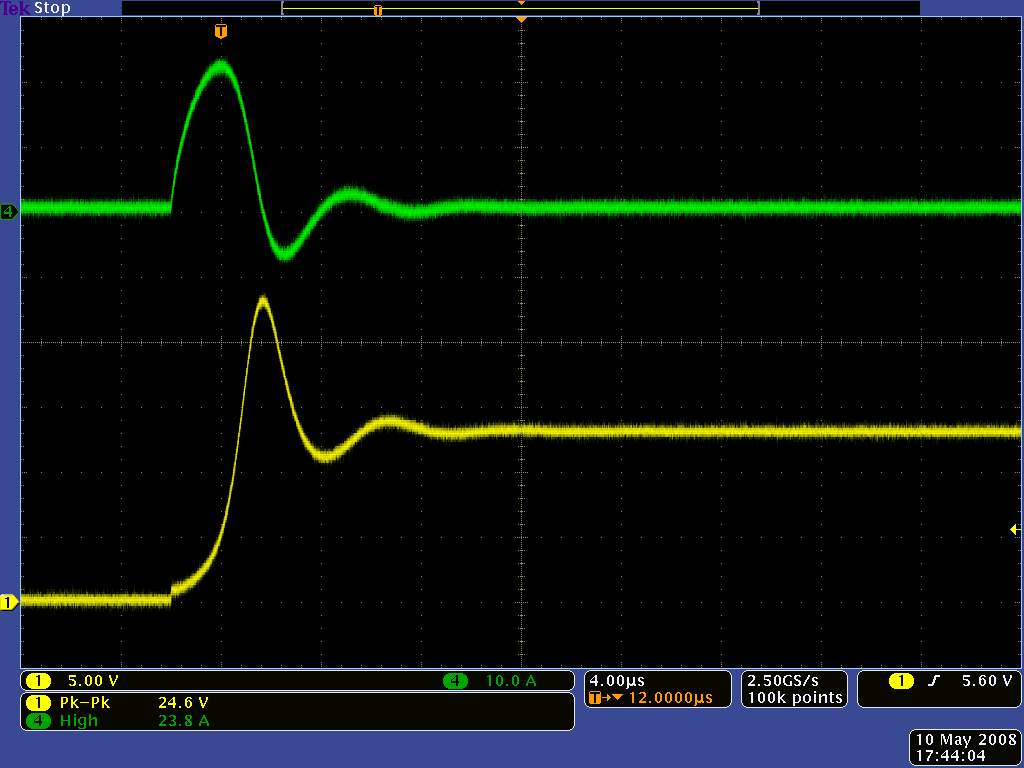 |
Oscilloscope capture of the voltage (yellow) and current (green) when using a battery with short leads. |
|---|
The charged battery voltage is over 13 V, so the 25 V peak we see here is now less than double the voltage we’re intending to apply. It could still destroy some components, but there are many more that can survive 25 V than can survive 40 V.
Adding Series Resistance
Unfortunately, we’re still left with a potentially destructive transient, and in cases such as the bench power supply, reducing lead length can be impossible or very inconvenient. The next thing we can consider is adding resistance in series with the power leads to limit the initial current surge. In low-power applications, even several ohms of resistance might be tolerable since the resulting voltage and power loss under typical conditions might be negligible.
However, adding resistance can be very undesirable in high-power applications. One option in such cases is to replace the instantaneous connection of a mechanical switch with the more gradual transition offered by an electronic switch, such as a MOSFET. We tested this approach with the Pololu pushbutton power switch, which is based on a MOSFET:
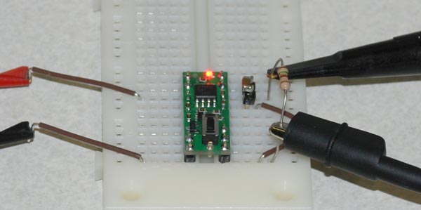 |
LC spike test setup close-up showing Pololu pushbutton power switch. |
|---|
The MOSFET does add a bit of resistance (typically around 0.01 ohms), but the important factor is the MOSFET’s gradual transition from non-conductive to conductive. With the mechanical switch replaced by a MOSFET, the 40-volt peak we saw was reduced to under 20 V:
 |
Oscilloscope capture of voltage (yellow) and current (green) when using the Pololu pushbutton power switch and bench power supply. |
|---|
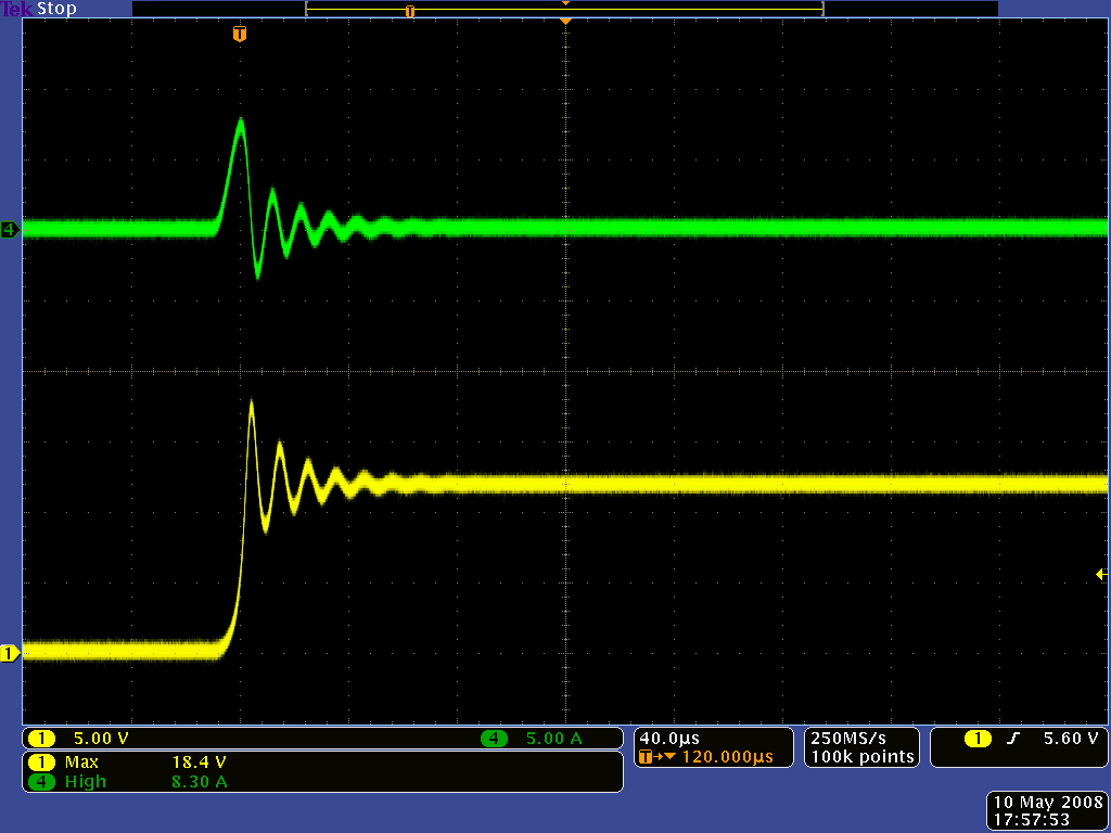
It’s worth noting that the circuit in the Pololu pushbutton power switch is not especially designed to turn on slowly, so an electronic-switch approach could completely eliminate the transient with a slower turn-on time. In the case of the Pololu pushbutton power switch, double-clicking quickly enough when starting in the on state (i.e. turning off and immediately turning back on) can cause the second turn on to be faster, leading to results more similar to those with the mechanical switch:
 |
Oscilloscope capture of voltage (yellow) and current (green) when “double-clicking” a Pololu pushbutton power switch connected to a bench power supply. |
|---|
We then combined the MOSFET-based approach with the reduced wire inductance of the battery test:
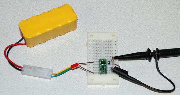 |
LC spike test setup with battery pack and Pololu pushbutton power switch. |
|---|
After seeing so many spikes, the near perfection of the transition is quite refreshing:
 |
Oscilloscope capture of voltage (yellow) and current (green) when using the Pololu pushbutton power switch and a battery. |
|---|
In the case of the Pololu pushbutton power switch, there is still the unfortunate (in this application) double-click possibility: after many attempts at getting the right timing, we were still able to catch some spikes, though they were much less severe than the 40 V peaks we saw earlier:
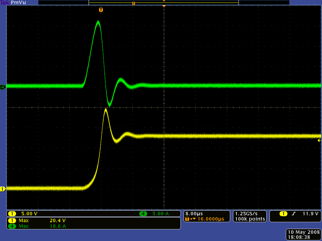 |
Oscilloscope capture of voltage (yellow) and current (green) when “double-clicking” a Pololu pushbutton power switch connected to a battery. |
|---|
Adding a Large, High-ESR Capacitor
We introduced the LC transient problem as being unique to ceramic capacitors with low equivalent series resistance (ESR). One particularly straightforward solution to the problem is to add a large capacitor with high ESR to the circuit. The large capacitor prevents the voltage from changing quite as quickly, yet its high ESR prevents it from drawing as much initial current. Here is the result when we added a 100 uF electrolytic capacitor in parallel with our 10 uF test capacitor:
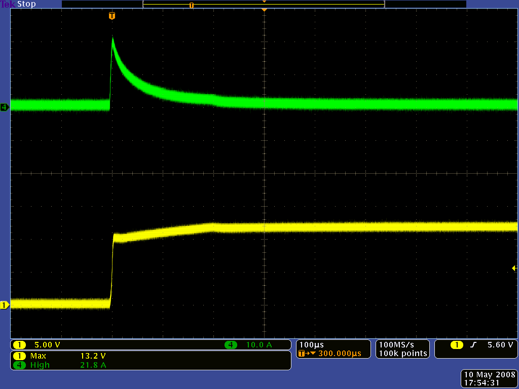 |
Oscilloscope capture of voltage (yellow) and current (green) when a 100 uF electrolytic capacitor is added in parallel with the ceramic capacitor. |
|---|
So, why not always use the large capacitor? When working on a large breadboard with a large power supply, there is little reason not to. However, in space-constrained applications, the capacitor might not be an option: one of the main appeals of the ceramic capacitor is its small size, and the necessary capacitor (it must have much higher capacitance and it cannot be the compact ceramic) might be larger than the rest of the circuit. It might also take some experimenting to determine the input capacitance of an unknown device and to see which external capacitors have the right ESR.
6. Conclusion
We have shown that power-up transients induced by the interaction of high wire lead inductance and low capacitor equivalent series resistance (ESR) can be destructively large. The phenomenon can be especially frustrating for those getting started in electronics because the mere application of power, even with the correct polarity and with a seemingly safe voltage, can destroy a circuit before it ever begins functioning. Repeated voltage spikes outside of maximum ratings can also gradually weaken components, leading to early failure that is difficult to explain: a circuit might function normally for some time before unexpectedly failing after a power cycle.
We hope that this application note raises awareness of the issue and presents practical techniques for avoiding the transients in your future projects. We would appreciate your feedback; if you have any comments, please post them to this forum topic.
Related products


Home | Forum | Blog | Support | Ordering Information | Lists | Distributors | BIG Order Form | About | Contact
© 2001–2026 Pololu Corporation
