Support »
Tamiya “Toy” Motor Testing by Adam Borrell (a.k.a nexisnet)
View document on multiple pages.
You can also view this document as a printable PDF.
- 1. Introduction and Experimental Setup
- 2. Initial Results: Motors Running at 7.2 and 6 V
- 3. Results for Motor Running at 5 V
- 4. Results for Motors Running at 4 V
- 5. Final Results: Motors Running at 3 V
- 6. The Verdict
1. Introduction and Experimental Setup
This information has been copied from Adam’s thread Tamiya ‘toy’ motor testing on the Pololu robotics forum.
A lot of people, myself included, are interested in just how high you can push the voltage on the motors in the small Tamiya gearboxes. I would be happy to halve the operating life of my gearbox if it means being able to run the motors faster, especially if I can run them straight from a greater-than-5V battery pack, so long as that half-life is still longer than I plan on using the motor. Lets say 20 hours of continuous operation would make me happy, and 50 would make me very happy.
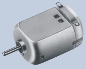
Unfortunately, since these are small ‘toy’ motors, the manufacturer really doesn’t offer any cycle-life numbers, even when operating the motor at the recommended 3V or less. I happen to have a bunch of Mabuchi FA-130s around, those are the motors that the 70168 Double Gearbox, 70167 Single Gearbox, 70097 Twin-Motor Gearbox, 70093 3-Speed Crank-Axle Gearbox, 70110 4-Speed Crank-Axle Gearbox, and 70103 Universal Gearbox are based on. Recently I’ve been doing a little testing with these motors, basically I’ve been running them into the ground…in a controlled, pseudo-scientific way of course:
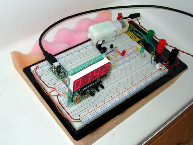 |
For light loading and downgearing, I’m fitting the test motors into the Solarbotics GM9 gearbox (143:1 reduction). The gearbox output shaft is turning a piece of card-stock which interrupts a photo-gate once per revolution. It looks like the gearbox is just sitting there, but I super-glued it to a chip socket so it presses in place on the breadboard. The photo-gate interruptions are counted by an ATTiny2313, which drives an LED display (readout in RPM) and transmits the speed readings over a serial connection to a laptop. The motors will all be driven in the same direction at a constant voltage, straight from a regulated DC power supply, working only against the internal resistance of the gearbox.
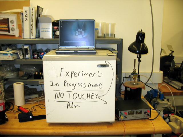
The first thing I noticed is that running the motor way over the recommended voltage makes it even more loud and annoying than these gearboxes normally are, which might be a consideration for some robots. To keep from driving myself crazy, I’m conducting these experiments with the breadboard on a piece of foam inside a (room temperature) minifridge (it REALLY helps!).
 |
The second thing I noticed about overpowering these motors was that they generate some horrendous electronic interference. The motor is powered from an isolated output of my power supply, and I added capacitors across the motor leads, but the USB-Serial adapter kept flaking out whenever I was running the motor (the LED would flicker and my laptop would stop receiving data). I even tried surrounding the adapter in grounded foil, but I eventually had to cut it out of the setup. Instead I ran the TTL serial TX line from the ATTiny through a logic inverter and into my laptop’s serial port. Neither the inverter chip nor the AVR seem affected by the interference, but still watch out (and use those capacitors!).
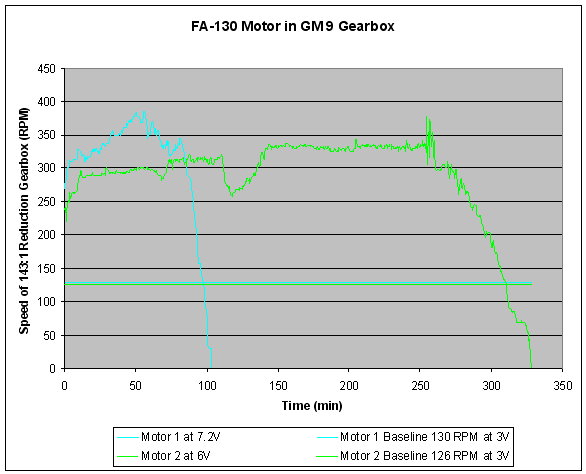
2. Initial Results: Motors Running at 7.2 and 6 V
So far the data is less than encouraging (at least for us fans of 7.4V LiIon packs). I started out at 7.2V, the nominal voltage of a 6 cell NiMH or NiCd pack, and just under the nominal voltage of a 2 cell Lithium Ion or Lithium Polymer pack (my favorites). The motor was dead after one hour and 44 minutes. Not temporarily overheated, not slowing down, dead dead. When I took it out of the gearbox the shaft still spun freely, but it wouldn’t turn under power, even with no load, and here’s why:
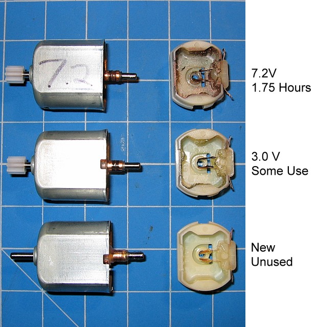 |
In the picture above, the bottom motor was never used at all (sacrificed in the name of science!). The brushes and commutator (the brush-contact barrel) are pristine, shiny, and well-lubricated. The middle motor is one I had used for some amount of time, but only ran at or below 3V. There’s some grit in it, but the commutator is still smooth and the brushes are in fine shape. The top motor is the one I ran at 7.2V. There are grooves maybe 20 thousandths of an inch deep on the commutator, and the brushes are seriously damaged, by which I mean that one brush is just plain gone! There is also copper dust spattered all over the inside of the casing. Less than two hours earlier this was a brand new motor, just like the bottom one in the picture. Wow.
I just finished testing another motor at 6V, which did a little better, lasting for five hours and 28 minutes. It now looks the same inside as the 7.2V motor. It’s even the same brush that’s missing (the one I had connected to power, if that makes a difference), which leads me to believe that the damage is caused by arcing, and more severe in one direction. If you run your motor in reverse some of the time it may last longer, but both brushes are damaged so it probably won’t double the life. I don’t think the wear is caused by friction directly, since the 6V motor lasted for almost three times the number of actual rotations of the 7.2V motor. Anyway, here’s the performance data I have so far:
 |
3. Results for Motor Running at 5 V
The five volt motor made it through the night, and died after 15 hours and 31 minutes, getting in a respectable 240,232 rotations. Same mode of failure as before, but this time it’s the other brush that’s missing (although I’m not 100% sure that I hooked up power in the same direction as the first two). There seems to be some sort of logarithmic trend going on:
 |
4. Results for Motors Running at 4 V
The vaguely logarithmic trend of motor life tripling for each volt less may be over.
Something went catastrophically wrong with the first motor I tested at 4V, its speed started slowly dropping at around eight hours, and it died right around 14 hours (an hour and a half LESS than the 5V motor). I tested another motor at 4V, which has a failure curve that looks much more like the previous tests, but it only lasted about 17 and a half hours, just two hours longer than the 5V motor.
The stats so far:
 |
My guess is that at higher voltages, arcing is the primary source of brush and commutator damage, but at these lower voltages and longer lifetimes heat and friction are limiting the time and cycle life as well. The motors all look the same inside in the end, but at lower voltages the motors also seem to be venting smoke, which builds up as soot on the windings and motor cases. It may be that this happens all the time, but at higher voltages there is less time for the soot to build up.
5. Final Results: Motors Running at 3 V
Well the testing is all done, and the results speak for themselves.
The Results:
 |
There is a pronounced operational lifetime shortening as you increase the voltage (no surprise). Also, I had trouble with a couple of individual motors. Again, the first motor I tested at 4V (purple) died an early, but long and drawn out death, so there may have been some defect in it to begin with. The first motor I tried at 3V (dark blue) kept stopping short, but would mysteriously come back to life (and full speed) hours later, when no one had so much as opened the mini-fridge. I took it apart and found that the brushes were in fine shape, but the grooves had already started to form in the commutator and were full of soot. So, if you’re having trouble with a motor stopping for no good reason, a blast of compressed air or some non-conducting lubricant (i.e. white teflon grease) through the vent in the plastic cap could make all the difference.
Speaking of difference, how does all this compare to the motor’s performance at 3V (the recommended peak voltage)? Wow:
 |
Seriously! Stepping up to 4V from 3V cut the operational life down to less than 1/4 of nominal! Another way to interpret the data is to look at the relationships between them normalized to the 3V motor values, since these relationships should (ideally) hold for any gearing/loading (I defined the end of the “useful lifetime” as when the output speed drops past half of the overall average speed):
 |
There is a vaguely logarithmic relationship after all, and besides, every technical presentation needs at least one chart with a log-scale axis:
 |
6. The Verdict
If you want more speed, you can have it, but will pay dearly for it in decreased operational life. That isn’t to say don’t do it, keep in mind that most hobby robots are run in short bursts infrequently, and you can replace the motors (Pololu sells them for $1.99). It looks like somewhere between 4 and 5 volts gives you the best payoff, but beyond that you’re really doing some damage. Speaking of damage, I have a nice little motor graveyard going on my desk:
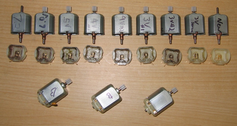 |
Since this article was first written, Pololu has started selling a similar 130-size motor ($1.79) that is designed for operation at higher voltages (3 – 12 V) and draws under an amp when stalled at 6 V. These motors can be used to replace the Mabuchi FA-130 motors in Tamiya gearboxes for lower-current or higher-voltage applications. These motors also produce less electrical noise than the Mabuchi FA-130 motors.
Related products


Home | Forum | Blog | Support | Ordering Information | Lists | Distributors | BIG Order Form | About | Contact
© 2001–2026 Pololu Corporation
