Pololu Blog »
The Rebel WIP from UNLV
 |
It has been over a year since my last/first blog post about my mini sumo robot. Since then, I have been busy studying to earn a mechanical engineering degree at the University of Nevada, Las Vegas, working at Pololu, and, of course, building cool robots. Recently, I have been working as part of a UNLV team, Rebel Robotics, to build a robot to compete in an intercollegiate competition organized by the American Society of Mechanical Engineers (ASME) called the Student Design Competition. My team’s robot, the Rebel WIP (work in progress), competed against teams from colleges across the western half of the United Sates in the Student Design Competition at an engineering festival hosted by UNLV and ASME called E-Fest West.
The competition
The challenge presented in the Student Design Competition is different every year. This year, the challenge was to build a robot to compete in a series of five events called a Robot Pentathlon. The events included a sprint, a stair climb, a lift, a throw, and a hit. The robots had to start each event in a 50 cm sizing cube and could only use energy from a rechargeable battery. The robots would compete and be placed first-to-last in each event based on their performance. The sum of the places determined the winners of the competition (lowest sum won).
Chassis and drive train for sprint and stair climb
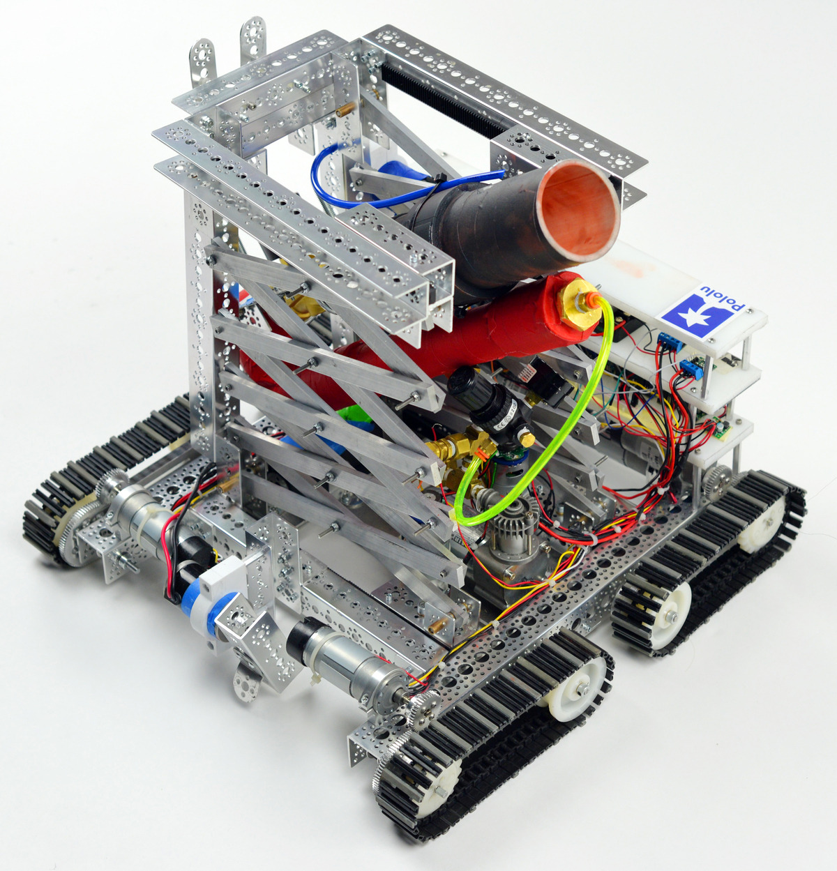
The chassis is built from ServoCity and Tetrix C-channel sections bolted together with corner-brackets. These brackets hold the frame together, but to keep the frame stiff we machined a steel plate that mounts to the underside of the robot and supports other components like the air compressor and battery.
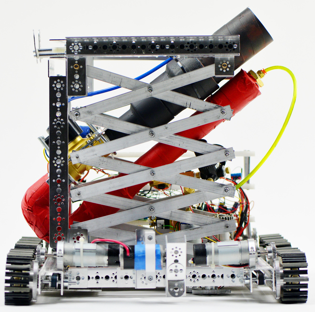
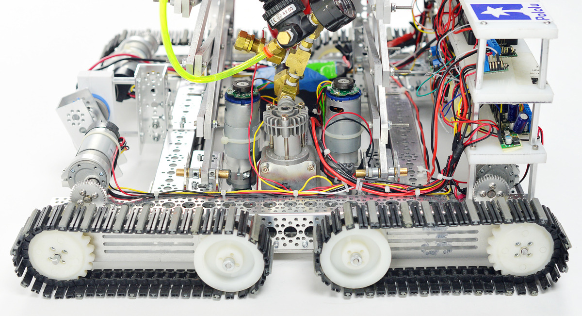 |
The Rebel WIP’s frame, side view. |
|---|
For the sprint event, robots had race against time to touch a wall ten meters away and get back to their starting location. In the stair climb, the robots had to ascend and descend a set of three steps as quickly as possible. The steps could each be up to 15 cm high. To make the Rebel WIP competitive in both the sprint and the stair climb, my team designed a differential drive setup to control four tank treads that are each on independently articulated tank arms.
The four tank treads are controlled by two motors at the back of the robot. They are the motors that are in line with the C-channel chassis, not the motors above the chassis. By directing these motors to rotate in the same or opposite direction, the robot will move backwards, forwards, or turn. To make this work, the output shafts of two motors are coupled to 6 mm shafts which are supported by bearings in the C-channels. Each of these shafts at the back of the robot are fixed to a timing belt pulley on the inside of the C-channel and a hub which rotates the rear tank tread. The timing belts on each side run to pulleys at the front of the robot that are also fixed to rotate with 6 mm shafts. These shafts at the front of the robot are fixed to hubs that rotate with the front tank treads.
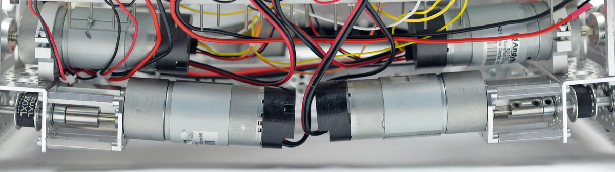 |
Drive and tank arm motors located at the back of the Rebel WIP. |
|---|
The tank arm articulation system is closely linked with the drive system. The tank arms support the tank treads and can rotate about the driving pulleys. They are able to do this independent of the movement of the treads. The aluminum tank arm parts were machined from a larger plate using a CNC (computer numerical control) mill at the UNLV machine shop.
Actuating the tank arms requires four more motors. These four motors sit above the C-channel frame at the front and back of the robot. Each motor drives a small gear that connects to a larger gear fixed to an aluminum arm. The large gear moves together with the aluminum tank arm. A second milled aluminum part sits in a slot in the tank arm. This part supports the idler pulley for the tank tread. Positioning this support in the slot tensions the tank tread. The aluminum tank arms are supported by, but not fixed to, the 6 mm shafts that drive the tank treads. The gears that are fixed to the tank arms and control tank arm rotation are concentric with the 6 mm shafts and drive pulleys. When one of the motors above the frame rotates, the arm it connects to will rotate around the shaft that supports it, but the parts fixed to the shaft (the tank tread and pulleys) do not rotate with the arm.
 |
Forward tank arm in angled position. |
|---|
During the competition, the articulation of the tank arms allowed the Rebel WIP to approach a step and prop itself up on the raised surface. Rotating the rear treads behind the frame kept the robot supported while it climbed the stairs so that it would not tip over backwards. There were a few flaws in the drive/climbing system that could not be corrected in time for the competition. The motors selected were just barely powerful enough to complete the tasks under ideal circumstances, but were not powerful enough to complete the tasks reliably. We should have either used more motors, or more powerful motors. In fact, the robot had trouble turning because the drive train motors did not have enough power to pivot the robot from a stopped position. Fortunately, we did not need to turn in any of the events. Another problem was that a few components on the robot were too low on the robot and could obstruct the robot from climbing. It also would have been better if we programed the tank arm motors to hold position under load when not being controlled using encoders, but we ran out of time to do this before the competition. The most significant problem with the chassis was that the steel plate caused the frame to bow. The plate had been machined by hand, so some of the designed dimensions were not produced with adequate precision. Despite these shortcomings, the Rebel WIP earned second place in the sprint event, and tied for third in the stair climb event.
The lift
In the lift event, robots had to lift a weight as heavy as possible as high as possible in under one minute. The score used to rank the teams was calculated by multiplying the weight lifted in kilograms and the distance lifted in centimeters. To accomplish this task, the Rebel WIP uses two scissor lift mechanisms to raise a platform that holds a weight. The platform is made of a few sections of C-channel that go around the air cannon, which I will discuss later.
Each scissor lift mechanism is supported at two points at the base of the robot. At one point the connecting scissor lift section can rotate on a bushing but otherwise cannot move. The second point also allows the connecting section to rotate on a bushing, but it can also translate linearly towards or away from the first connection point. This is accomplished using a rack and pinion system connected to a motor geared for high torque. The rack and pinion is setup so that when the motor rotates, a small C-channel section will move linearly on along the gear rack. The motor and the second connection point for the scissor lift are fixed to the moving C-channel section. The same connections are present at the top of the lift, just without the motor.
When the pivot points are moved towards each other, the scissor lift sections, which are connected to each other at their ends and midpoints, are forced to rotate so the lengths of the sections create a greater angle relative to the horizontal. The total length of each scissor lift section is fixed, so as the horizontal component of the space each section covers from end to end shrinks, the vertical space each cross section covers must expand, increasing the total height of the structure.
The two scissor lift mechanisms on the Rebel WIP need to move together to keep the top platform level. We could have done this by using encoders to keep the motors running at the same speed, but it was simpler with our time constraint to make a control option where the two lift motors could be controlled independently. If one motor got ahead of the other, we could manually stop it with the remote control and give the other motor time to catch up.
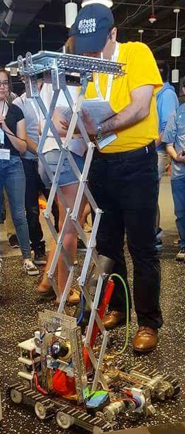 |
The Rebel WIP completing the lift at competition. |
|---|
Building and testing the scissor lift was a significant learning experience for me and my team. Our goal was to lift a relatively light weight and maximize height. This strategy required the robot to have as many scissor lift sections as possible, but each section added to the lift adds weight that the motor has to lift. More importantly, the more scissor lift sections add to the starting inertia that the motor must overcome to get the lift moving, especially in our ideal setup where the sections start nearly parallel to the horizontal. For these reasons we expected motor power to be the greatest limiting factor to improving the lift. Instead, we discovered that the it was our structure around the motor and lift that could not handle the heavy loads caused by the scissor lift actions. Parts of our structure would deform under load and space would form between external gears that connected the motor to the rack and pinion. This would cause the gears to start skipping teeth, which would stop the lift right after it only started to raise the weight. To make the lift work for competition we had to dramatically reduce the number of sections used in the scissor lifts since we did not have time or budget to build a new stronger frame structure.
For the competition, the Rebel WIP lifted a relatively light weight of about 1 kilogram about 1.7 meters. Although our lifting capacity was far less than our goal, we still lifted our weight higher than any of the other robots.
The throw
In the throw event, robots had to throw a preloaded tennis ball as far as possible. The loading and throw had to be completed in one minute. The Rebel WIP completed this event by using compressed air to launch the tennis ball through a PVC tube. An air cannon is a pretty simple concept, but a lot of thought went into optimizing each element of the design to maximize the throw distance. A regulation tennis ball is 2.7 inches in diameter, so we selected 2.5 inch PVC for the cannon to have a tight fit. Tennis balls have a small amount of compression, but our fit was tight enough that a ramming rod had to be used to load the tennis ball into the cannon. Since all the power for the robot had to come from a rechargeable battery our robot needed to use a compressor to build air pressure. In the competition we would launch the tennis ball around 100 psi. This high pressure can be dangerous to work with if you’re not careful, and you definitely do not want to accidentally exceed the safe operating pressure you establish. Rebel WIP has multiple safety components including a pressure gauge, manual pressure release valve, a pressure switch, an air pressure regulator, and a relief valve. Our air reservoir was located right next to the one inch electric valve that would open to launch the tennis ball, and our valve was located just before the cannon. Minimizing the space between the reservoir, valve, and cannon were important design considerations because we wanted the compressed air to be moving with as much force as possible when it contacted the tennis ball.
|
|
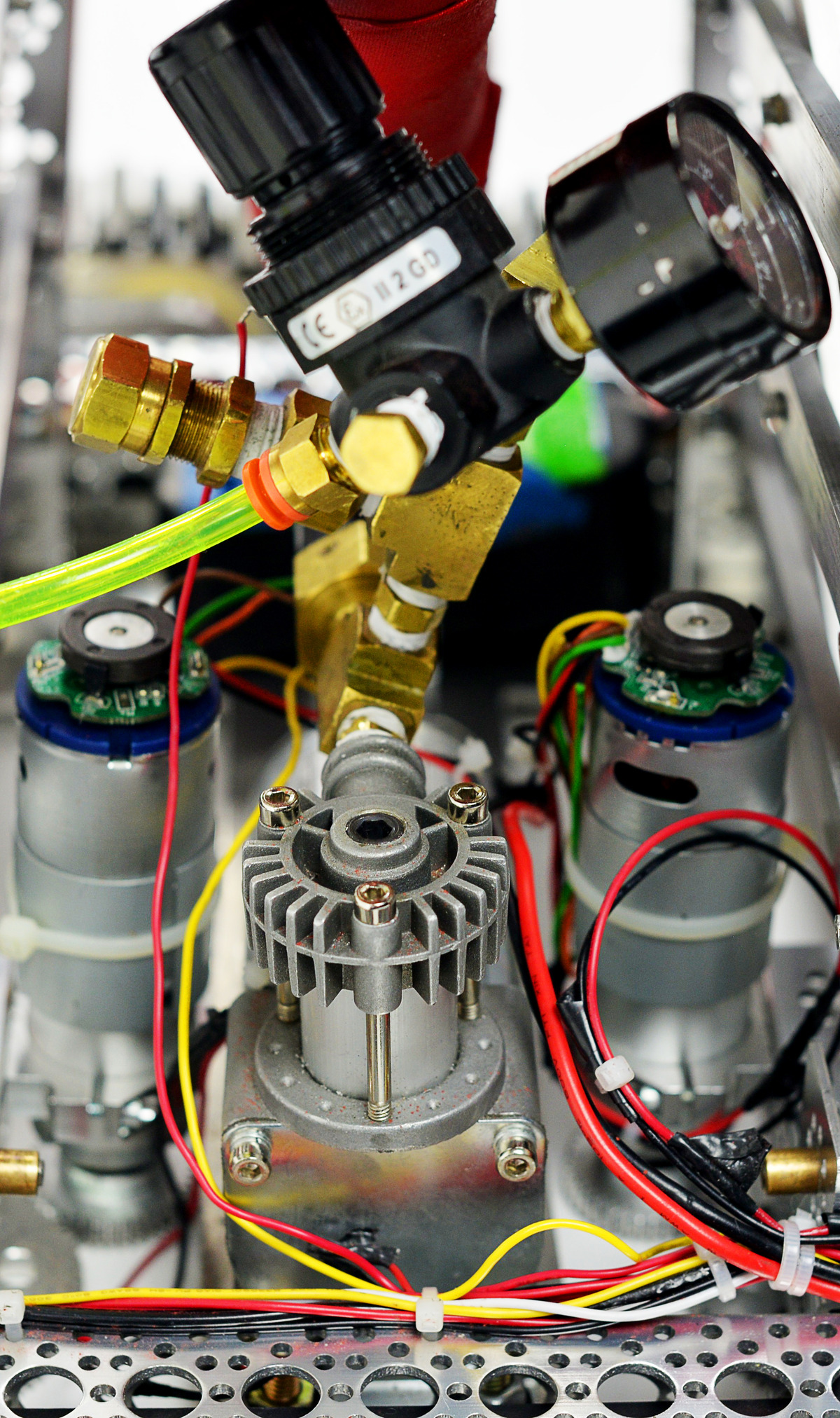
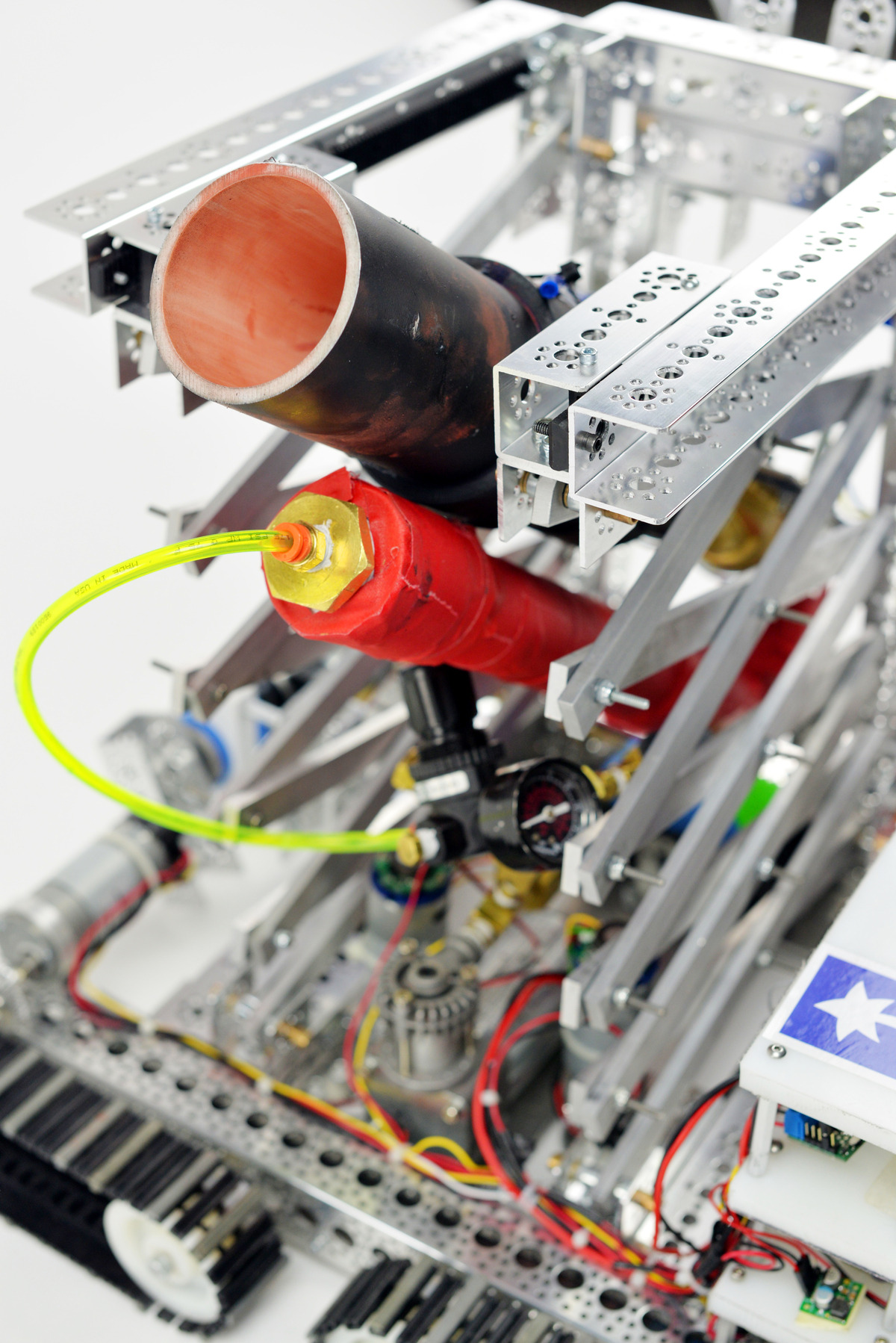
At the competition, the tennis balls were covered in red chalk so that the ground would be marked where the balls first land. So after the loading and firing the first tennis ball, the PVC white color on the inside of the cannon was replaced by a cool coat of red chalk. The Rebel WIP threw the tennis ball over 145 feet in the competition. We earned second place in this event.
The hit
In the hit event, robots had to hit a golf ball that started on the ground as far as possible in a straight line. The score used to rank the teams was the distance the golf ball traveled before hitting the ground in the specified direction minus the distance the golf ball traveled perpendicular to the specified direction. To complete this event, the Rebel WIP has a powerful motor at the front of the robot without any gearing to reduce the speed of the motor. It has a free run speed of 13,180 rpm. Attached to the motor output shaft was a piece of metal to hit the golf ball. The strategy was to prop up the front of the robot using the front tank arms, turn on the front motor, allow it enough time to reach to full speed, then move the tank arms to come down and hit the golf ball.
 |
The Rebel WIP, front view. |
|---|
My team and I thought of the hit as the least interesting and most difficult of the challenges. It became the lowest priority challenge for our team and was the last component to be tested. In fact it was not tested until around 12:30 am the day of the competition. Unsurprisingly, the mechanism for completing the hit did not work during the competition and our team tied for last place in that event. Fortunately, our performance in other events compensated for our weak performance in this event.
Electronics
The Rebel WIP is powered by a 12 V rechargeable battery. We selected the Arduino Mega as the microcontroller for the robot because we could use the familiar Arduino IDE to program the robot, and the Mega has 70 input-output lines available to control the many components on the Rebel WIP. When fully charged, the battery voltage is usually around 14 V, so a Pololu 9V step-up/step-down voltage regulator is used to reduce the voltage supplied to the Arduino (the recommended range for powering Arduino microcontrollers is between 7 V and 12 V). The robot is operated remotely using a PlayStation 2 controller. The controller’s wireless receiver is connected to digital inputs on the Arduino. The receiver is powered through the Arduino’s on-board 5 V regulator. Whenever the Arduino is powered (even if the rest of the robot is not powered), the receiver is also powered, so I can send signals to the robot with the remote control. This was useful for troubleshooting problems when I began programming.
The motors for the drive train, tank arms, and lift are controlled by Pololu second-generation high-power motor drivers. The motors for the drive train and tank arms are each controlled by a 24v13 motor driver. The two lift motors are each controlled by a 18v25 motor driver. The motor used for the hit event is controlled by an old Talon SR motor controller I had previously used for an FRC robot when I was in high school. I used the digital inputs on two high-power MOSFET slide switches to activate the air cannon valve and to turn the air compressor on or off. The Rebel WIP also has a Pololu 5V step-down voltage regulator that could have been used to power many small components like encoders in case the Arduino’s on board regulator could not supply enough power. Unfortunately, I did not have time to add these components before the competition.
The battery is wired in series with a physical switch that powered the rest of the components (regulators, MOSFET switches, and motor drivers) in parallel. This means that when the switch is turned on, all of these components can draw power from the battery without that power having to go through any other circuit elements except for the battery’s built in fuse.
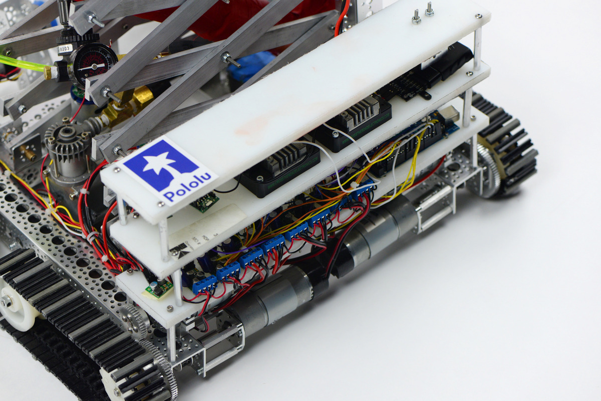 |
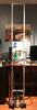
The electronics shelves on the Rebel WIP. |
|---|
All of the electronics for Rebel WIP are located on two shelves at the back of the robot. When I build robots under a size constraint, I like stacking my electronics like this because it allows me to keep all the electronics consolidated in one area, but it is not as demanding on horizontal space as making one board that carries all the electronics. It also allows me to keep all the jumper wire connections vertical. This way when the robot moves around, gravity is working to help keep things connected instead of actively working to break connections.
Results
The Rebel WIP was a time consuming project, especially as the competition date drew closer and closer. My team’s hard work paid off though. We won third place out of thirteen university teams in the competition!
Any robotics project is a learning opportunity, and I certainly learned a lot from working on the Rebel WIP that will help me improve my other robotics projects. Although my next big task at hand is preparing for finals in May, I look forward to sharing my next cool robot project.
Related products


-
Balancing robot with stepper motors
- 10 April 2017One of our customers built this six-foot tall balancing robot. The main microcontroller is a Teensy 3.6, and the stepper motors are driven by...
-
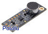
Verbal Machines VM-CLAP1 Hand Clap Sensor
- 14 April 2017Don’t hold your applause: we are now offering the Verbal Machines VM-CLAP1 Hand Clap Sensor! This board is a low-power, microprocessor-based audio...
0 comments
Post a comment


Home | Forum | Blog | Support | Ordering Information | Lists | Distributors | BIG Order Form | About | Contact
© 2001–2026 Pololu Corporation
