Pololu Blog » Engage Your Brain »
How an idea becomes a product
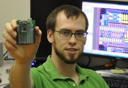 |
Wixel shield and not me. |
|---|
The Wixel Shield for Arduino that we released today represents a personal milestone because of what I did not do on it: the shield is the first electronic product made by Pololu that I did not design. That’s not to say I did not have some input on it or that other engineers here did not have substantial contributions to other products, but the Wixel Shield is a first because the basic product concept, the circuit design, and physical implementation (i.e. the PCB layout) were all done by someone else. We also just finished a big facility expansion that was taking up a lot of my attention this year, so I have some more time now to think about our design process and what it takes to go from a new idea to a finished product.
At first glance, we design something, then we make a bunch of units, and sell them:
 |
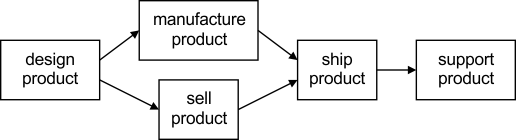
If I think about our facility, it’s clear we put a lot of effort into other aspects of getting a product out to customers, so I’ll add shipping and support to the diagram:
 |
This is not always the order in which we do things. When we do some custom product development (which is almost always a customization of an existing product), we might make the sale first and then hope we can deliver what we promised:
 |
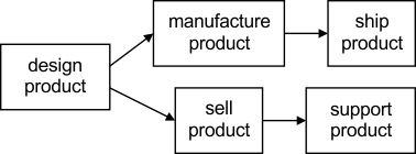
This “sell-first” approach can be kind of dangerous and is a topic I might discuss in some future post. For now, I’m focusing on the typical case, where we first design something and then sell it. Still, the observation that the sale can happen somewhat independently of the actual making of the object being sold holds, which leads to this kind of picture:
 |
Here, we see that manufacturing and marketing can happen somewhat independently, but both need to happen before we can ship a product, and both are dependent on the product first being designed. As soon as I have two paths, with manufacturing and marketing in parallel, the limitations of my diagram become obvious. The diagram is basically chronological from left to right, but is it saying manufacturing and selling are both prerequisites of shipping, or are they alternate paths? And is there anything special about arranging things chronologically? If I want to think about some kind of information dependencies, this kind of drawing might be better:
 |
It might be difficult to get rid of the chronological mindset, but the idea now is that selling and shipping are not dependent on each other in terms of information about a design. I am not sure if this is the best way to arrange the five boxes, but it might suggest that after we design a product, some information has to go to manufacturing to make the product and other information has to go to those selling and supporting the product.
Part of the point of the first few diagrams is to try to think about and notate what we do here in some fairly simple terms. If we don’t have a good picture of what we’re supposed to be doing here, how can we tell if we are doing it well, or if we are even doing what we think we are doing? Yet, even with just those few blocks, it’s difficult to represent how various things we do here are related.
Despite my difficulties getting something particularly meaningful out of the large-scale diagram, I started thinking about just the “design product” box. I know there are a bunch of specific steps involved, so that might be easier to show in a diagram. Or maybe not:
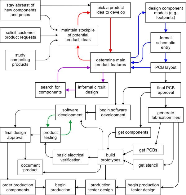 |
Not only does this diagram have many more elements (with several complex processes such as “document product” represented with just one box), it has all kinds of loops (the arrows are colored to make the loops easier to see). And I didn’t even draw all of the loops since just about any box toward the bottom of the diagram can link back to the first loop if we run into some kind of a problem that requires a substantial redesign of the product. I broke up two of the more complex sub-processes, software development and production test development, into two boxes each to call out that we can begin work on them without a physical prototype but ultimately cannot move on from those steps until we have real units to test.
Not that long ago, I was doing all of these blocks, which made the exact order or how they are interconnected much less relevant because I could basically do various aspects of development in parallel. The designs also were not that complicated, so I could mostly keep track of everything in my head without extensive internal documentation. As our designs get more complex and as more people get involved, it is becoming more important to figure out the various dependencies. We do not want to do most of the work and then find out that we cannot make the product yet because a test system is not ready, but we also do not want to make the tester until we have a very good idea of what the product will be.
I suspect that a lot of what leads to a good design is captured in the intertwining loops that go through the “determine main product features” box: the design goes through many iterations where we consider everything from which parts to use to how many mounting holes the product should have. Unfortunately, the loops also make it more difficult to break up the design process into neatly separated sub-processes. For example, layout of the PCB might seem like an easy step to hand off, but there are all kinds of little decisions we have to make when we actually implement things down to the details. There can be many non-essential features that might not be worth making absolute requirements in an earlier design step but which can be added essentially for free if the PCB designer has a good understanding of what the product is supposed to be.
Some of what we need to go through is analogous to switching from writing programs in assembly language to writing them in a higher-level language. When microcontrollers were more expensive and had fewer features, writing firmware in assembly was important to meeting the level of optimization we needed to make a product feasible. For almost all of our new products now, we just start with a microcontroller that has enough resources to make it practical to program in C, and we accept that getting the most we can out of the microcontroller is not that meaningful of an optimization. I like to think that our products are optimized similarly to a good assembly program that gets the most possible use out of the available hardware. That product optimization might manifest itself as the smallest PC board we could make using a particular manufacturing technology (e.g. 2-layer PCBs) or as the product offering the most features possible as a function of our manufacturing cost. But, as with the assembly program and as indicated by the mess of interconnections on the design process diagram, this optimization comes at the cost of development time, and the approach might be very difficult to scale to more complex products. As we move to a more structured development process, our challenge is to find the equivalents of C and decreasing microcontroller costs: a process that does not really limit what we can create and the output of which deviates from optimal only by a factor we can compensate for in some other way. For instance, new, less optimal designs might use larger quantities of unique components, which would generally increase costs, but that could be offset by our component prices coming down due to our increased overall volume.
I do not have an exact count, but I have made over 120 different PCB designs and revisions, which averages out to about one new product per month for the past ten years. If we want to keep growing, that rate will have to go up, and the measure of success for our engineering department will be how many designs we can complete while maintaining or improving the quality of our products. We have no shortage of product ideas (there are dozens of product ideas in that red loop in the diagram), and our throughput is easy to measure; judging the quality or optimality of the final product is more difficult. I expect to discuss some of our design principles in future posts, and I welcome any feedback you have about the quality of our designs, what you look for in a good design, and how you achieve good designs in your projects or organizations.
-

Rotating monitor for arcade cabinet
- 16 June 2011This rotating monitor for an arcade cabinet uses a Simple Motor Controller, a gearmotor with encoders and a Pololu wheel to control the rotation.
-
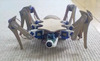
Low-cost hexapod
- 24 June 2011A Mini Maestro 24-channel USB servo controller controls three servos in each of this insectoid robot’s six legs. For more information, see this...
0 comments
Post a comment


Home | Forum | Blog | Support | Ordering Information | Lists | Distributors | BIG Order Form | About | Contact
© 2001–2026 Pololu Corporation


