Support » Jrk G2 Motor Controller User’s Guide »
13. I²C command encoding
This section documents how the Jrk G2’s commands are encoded as a I²C transactions.
Number prefixed with “0x” are written in hexadecimal notation (base 16) and numbers prefixed with “0b” are written in binary notation (base 2). Numbers with these prefixes are written with their most significant digits first, just like regular decimal numbers.
The default slave address for the Jrk is 0b0001011 (0x0B in hex, 11 in decimal). The address is equal to the least-significant 7 bits of the “Device number” setting, which you can change in the Jrk G2 Configuration Utility.
As specified by the I²C standard, a transfer’s first byte consists of the 7-bit slave address followed by another bit to indicate the transfer direction: 0 for writing to the slave, 1 for reading from the slave. This is denoted by “addr + Wr” and “addr + Rd” below. With the Jrk’s default slave address, the address byte is 0b00010110 (0x16) for a write transfer and 0b00010111 (0x17) for a read transfer.
These symbols are also used in the descriptions below:
- S: start condition
- P: stop condition
- A: acknowledge (ACK)
- N: not acknowledge (NACK)
Any stop condition followed by a start condition can optionally be replaced by a repeated start condition.
For a reference implementation of the Jrk G2 I²C protocol, see the Jrk G2 library for Arduino.
For information about what these commands do and how to pick their parameters, see Section 11.
Set target (high resolution)
| master: | S | addr + Wr | 0xC0 + target low 5 bits | target high 7 bits | P | |||
| Jrk: | A | A | A |
The diagram above shows the sequence of signals on the I²C bus that comprise a “Set target” command. First, the master device initiates a start condition and transmits the byte containing the Jrk’s address along with a 0 bit to indicate that this transaction will be write transaction. The Jrk recognizes its own address and sends an acknowledgment bit for this first byte. Next, the master writes a byte that is calculated by adding 0xC0 to the least-significant 5 bits of the target value. The Jrk acknowledges this byte too. Then, the master sends a byte containing the lower 7 bits of the target value (the most-significant bit of this byte is clear). The Jrk acknowledges the byte (and performs the “Set target” command at this point). The master ends the transaction by performing a stop condition.
For example, a “Set Target” command that sets the target to 3229 (0b110010011101 in binary) for a Jrk using the default address would look like:
| master: | S | 0b00010110 | 0b11011101 | 0b01100100 | P | |||
| Jrk: | A | A | A |
Here is some example C code that will generate the correct bytes to send, given an integer target that holds the desired target (0–4095) and an array called i2cBytes:
i2cBytes[0] = 0xC0 + (target & 0x1F);
i2cBytes[1] = (target >> 5) & 0x7F;
Many motor control applications do not need 12 bits of target resolution. If you want a simpler and lower-resolution set of commands for setting the target, you can use the low-resolution command encodings documented below. Alternatively, you could use the high resolution version above with the lower 5 bits of the target always zero. Sending a 0xC0 byte followed by a data byte (0–127) will result in setting the target to a value of 32 multiplied by the data byte.
Set target (low resolution forward)
| master: | S | addr + Wr | 0xE1 | magnitude | P | |||
| Jrk: | A | A | A |
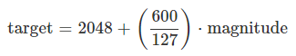
This is an alternative way to encode the “Set Target” command that provides less resolution and only works for target values of 2048 or greater. The target value is calculated from the magnitude byte (0–127) according to a formula that depends on what feedback mode the Jrk has been configured to use.
If the Jrk’s feedback mode is “Analog voltage” or “Frequency”, the formula for the target is:
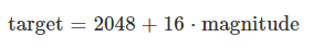 |
If the feedback mode is “None” (open-loop speed control), then the formula is:
 |
This means that a magnitude of 127 corresponds to full-speed forward, while a magnitude of 0 will make the motor stop.
Set target (low resolution reverse)
| master: | S | addr + Wr | 0xE0 | magnitude | P | |||
| Jrk: | A | A | A |
This is an alternative way to encode the “Set Target” command that provides less resolution and only works for target values of 2048 or less. It generally behaves the same as the “Set target (low resolution forward)” command encoding described above, except that the plus sign in each formula is replaced with a minus sign. The one exception is that if the magnitude byte is zero, then this command acts as a “Stop motor” command instead of a “Set target” command.
Stop motor
| master: | S | addr + Wr | 0xFF | P | ||
| Jrk: | A | A |
Force duty cycle target
| master: | S | addr + Wr | 0xF2 | duty cycle low 8 bits | duty cycle high 8 bits | P | ||||
| Jrk: | A | A | A | A |
This command takes a duty cycle between −600 and 600. The duty cycle is expressed as a signed 16-bit two’s complement number, with the lower 8 bits in the first data byte and the upper 8 bits in the second data byte.
For example, to send −300, first add 0x10000 to turn it into a non-negative number, yielding 0xFED4. Send the bytes in little endian order (least-significant byte first), as shown below:
| master: | S | addr + Wr | 0xF2 | 0xD4 | 0xFE | P | ||||
| Jrk: | A | A | A | A |
The following example C code shows how to generate the correct bytes, given an integer duty_cycle that holds the desired duty cycle (−600 to 600) and an array called i2cBytes.
i2cBytes[0] = 0xF2;  // Force duty cycle target
i2cBytes[1] = duty_cycle & 0xFF;
i2cBytes[2] = duty_cycle >> 8 & 0xFF;
Force duty cycle
| master: | S | addr + Wr | 0xF4 | duty cycle low 8 bits | duty cycle high 8 bits | P | ||||
| Jrk: | A | A | A | A |
This command is encoded in the same way as the “Force duty cycle target” command described above, except that the first byte is 0xF4 instead of 0xF2.
Get variables
| master: | S | addr + Wr | 0xE5 | offset | P | |||
| Jrk: | A | A | A |
| master: | S | addr + Wr | 0xE5 | P | (optional extra transaction allowed for SMBus compatibility) | ||
| Jrk: | A | A |
| master: | S | addr + Rd | A | … | N | P | |||
| Jrk: | A | data 0 | data length − 1 |
This command lets you read any of the Jrk’s variables, without clearing them or having other side effects. The offset byte specifies the offset into the variable data (in bytes). The master can read up to 15 bytes of response data from the Jrk. Multi-byte variables use little-endian format, so the least-significant byte comes first.
The second transaction shown above is optional, and should only be used if your master device is limited to using SMbus protocols. You can perform a “Get variables” command by first using an SMBus “Write Byte” transfer to send the Jrk G2 command and offset, then using an SMBus read transfer (e.g. Read Byte, Read Word, or Read 32) to send the same command byte and get the response data.
If you are using a clock speed faster than the standard 100 kHz, you should ensure that no activity happens on the bus for 100 µs after the end of a command like this one that reads data from the Jrk. Failure to do this could lead to I²C communication issues.
Get variables (one-byte commands)
| master: | S | addr + Wr | one-byte get variable command | P | ||
| Jrk: | A | A |
| master: | S | addr + Rd | A | … | N | P | |||
| Jrk: | A | data 0 | data length − 1 |
There are also several versions of the “Get variables” command which are limited to reading one or two bytes and only support some of the Jrk’s variables. Some of these commands will clear the corresponding variable as a side effect. The command bytes are listed below:
| Command byte | Response (and effect) |
|---|---|
| 0xA1 | Both bytes of the “Input” variable. |
| 0x81 | The low byte (least-significant byte) of the “Input” variable. |
| 0x82 | The high byte (most-significant byte) of the "Input variable. |
| 0xA3 | Both bytes of “Target”. |
| 0x83 | The low byte of “Target”. |
| 0x84 | The high byte of “Target”. |
| 0xA5 | Both bytes of “Feedback”. |
| 0x85 | The low byte of “Feedback”. |
| 0x86 | The high byte of “Feedback”. |
| 0xA7 | Both bytes of “Scaled feedback”. |
| 0x87 | The low byte of “Scaled feedback”. |
| 0x88 | The high byte of “Scaled feedback”. |
| 0xA9 | Both bytes of “Integral”. |
| 0x89 | The low byte of “Integral”. |
| 0x8A | The high byte of “Integral”. |
| 0xAB | Both bytes of “Duty cycle target”. |
| 0x8B | The low byte of “Duty cycle target”. |
| 0x8C | The high byte of “Duty cycle target”. |
| 0xAD | Both bytes of “Duty cycle”. |
| 0x8D | The low byte of “Duty cycle”. |
| 0x8E | The high byte of “Duty cycle”. |
| 0x8F | The “Current (low resolution)” variable (one byte). |
| 0x90 | The “PID period exceeded” variable (one byte). |
| 0xB1 | Both bytes of “PID period count”. |
| 0x91 | The low byte of “PID period count”. |
| 0x92 | The high byte of “PID period count”. |
| 0xB3 | Both bytes of “Error flags halting”. Clears the variable as a side effect. |
| 0x93 | The low byte of “Error flags halting”. |
| 0x94 | The low byte of “Error flags halting”. |
| 0xB5 | Both bytes of “Error flags occurred”. Clears it as a side effect. |
| 0x95 | The low byte of “Error flags occurred”. |
| 0x96 | The high byte of “Error flags occurred”. |
| 0x97 | The “Force mode” variable (one byte). |
| 0xB8 | Both bytes of the “VIN voltage” variable. |
| 0x98 | The low byte of the “VIN voltage” variable. |
| 0x99 | The high byte of the “VIN voltage” variable. |
| 0xB9 | Both bytes of the “Current” variable. |
| 0x99 | The low byte of the “Current” variable. |
| 0x9A | The high byte of the "Current variable. |
| 0xEC | The “Current chopping occurrence count” variable (one byte). Clears it as a side effect. |
Except for 0xEC, the command bytes in the table above all follow the pattern below:
| Read two bytes: | 0xA1 + offset | |
| Read one byte: | 0x81 + offset | |
Set RAM settings
| master: | S | addr + Wr | 0xE6 | offset | length | data 0 | … | data length − 1 | P | ||||||
| Jrk: | A | A | A | A | A | A |
The offset byte specifies the offset into the settings data in bytes, while the length byte specifies how many bytes of data to write. The length byte must be between 1 and 13.
For example, if you want to set the proportional multiplier (offset 0x51, length 2) to 984, you would convert 984 to hex (0x03D8) and send those bytes in little-endian order. The transaction would look like:
| master: | S | addr + Wr | 0xE6 | 0x51 | 0x02 | 0xD8 | 0x03 | P | ||||||
| Jrk: | A | A | A | A | A | A |
Get RAM settings
The encoding of this command is just like Get variables above, except the first byte of the write transaction(s) is 0xEA instead of 0xE5.
Get EEPROM settings
The encoding of this command is just like Get variables above, except the first byte of the write transaction(s) is 0xE3 instead of 0xE5.
Clock stretching
The Jrk G2 uses a feature of I²C called clock stretching, meaning that it sometimes holds the SCL line low to delay I²C communication while it is busy with other tasks and has not gotten around to processing data from the master. This means that the Jrk is only compatible with I²C masters that also support clock stretching. It also means that the time to send an I²C command to the Jrk is variable, even if you are only writing data and not reading anything.
The Jrk only uses clock stretching at most once per byte. It stretches its clock after it receives a matching address byte, after it receives a command/data byte, and after it sends a byte that is not the last byte in a read transfer. The Jrk will usually stretch the clock for 150 μs or less, depending on the timing of the I²C bytes and how busy the Jrk is performing other tasks.
Related products


Home | Forum | Blog | Support | Ordering Information | Lists | Distributors | BIG Order Form | About | Contact
© 2001–2026 Pololu Corporation
