Support » Pololu Simple Motor Controller User’s Guide » 5. Configuring Your Motor Controller »
5.3. Advanced Settings
The Advanced Settings tab lets you fine-tune the details of how your Simple Motor Controller behaves.
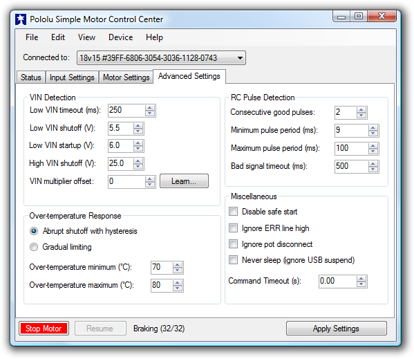 |
Advanced Settings tab in the Pololu Simple Motor Control Center. |
|---|
VIN Detection
These options specify how to measure the voltage on the VIN line.
The Low VIN options specify what constitutes a Low VIN error. A Low VIN error occurs when the voltage on the VIN line drops below the Low VIN shutoff voltage and stays below it for the amount of time specified by the Low VIN timeout. The Low VIN error will stop occurring when the voltage on the VIN line rises above the Low VIN startup voltage.
If you are using a battery that can be damaged by over-discharging, we recommend setting your Low VIN shutoff to an appropriate value so that your motors will shut down when the battery voltage gets too low. For example, if you are using a Lithium-Polymer (Li-Po) battery, it would be good to set a Low VIN Shutoff to something like 3.0 V or 3.5 V multiplied by the number of cells in your battery. You should also consult your battery’s specifications, and adjust your Low VIN shutoff based on how much current your motor draws and how careful you want to be.
If VIN exceeds the High VIN shutoff level, a High VIN error will occur. This error is different from the other errors: it instantly shuts down the motors and goes in to full braking mode, regardless of your deceleration and speed zero brake amount settings. This means that if you are using the controller in a differential drive vehicle and your vehicle is being pulled down a hill by gravity, the extra voltage generated by the motors might trigger a VIN error and the controller would attempt to stop your robot’s descent by braking.
The VIN multiplier offset is a calibration factor used in computing VIN. The default value of 0 should work fine for most purposes. If you have a multimeter or another accurate way of measuring voltage, you can click the Learn… button to have the software automatically set this number for you. If you find that the VIN reading shown in the Status tab is too high, you should decrease this number. If it is too low, you should increase this number.
Over-temperature Response
The Simple Motor Controller monitors its temperature using a sensor near the MOSFETs and protects itself from burning up by generating an error when the temperature is too high. The Simple Motor Controller has two modes for over-temperature response:
- Abrupt shutoff with hysteresis: This is the default mode. In this mode, the Over temperature error will start occurring when the temperature exceeds the Over-temperature maximum and will keep until the temperature drops below the Over-temperature minimum. In this mode, it will be obvious when you are having temperature issues because your motor will shut down completely while your motor controller cools off.
- Gradual limiting: In this mode, whenever the temperature is between the Over-temperature minimum and Over-temperature maximum, the magnitude of the motor speed will be limited. The speed limit is 3200 (100 %) when the temperature is equal to the Over-temperature minimum, and it decreases linearly with temperature so that the speed limit is 0 when the temperature is equal to the Over-temperature maximum. If the temperature rises above the Over-temperature maximum an over-temperature error will occur and the motor will stop. In this mode, the motor will keep on running as the board heats up, but it might run slower due to the temperature-based speed limiting.
RC Pulse Detection
These parameters adjust how lenient or strict the RC signal measurement is on the RC1 and RC2 lines. If you use strict settings, your controller will shut down faster when the RC signal is lost and be less likely to act on corrupted data. If you use lenient settings, your controller will be more likely to keep operating when the RC signal quality is poor.
Consecutive good pulses is the number of consecutive good pulses that must be received before the controller starts heeding good pulses and updating the channel value. The default value of 2 means that after 2 good pulses in a row are received, the third one will be used to update the channel value. A value of 0 means that every good pulse results in an update of the channel value. Increasing this number makes your settings more strict while decreasing it makes them more lenient.
Minimum pulse period and Maximum pulse period specify limits on the amount of time allowed between pulses. If a pulse is received too soon after a previous pulse, it is considered bad. If the pulses on the line stop, then the RC input channel’s signal is considered invalid after an amount of time equal to the Maximum pulse period has elapsed. The period of your RC signal is shown in the Status tab, so you can use that to help pick good values for these settings.
The Bad signal timeout is like an expiration time for the pulses. If the RC signal line is corrupted by enough bad pulses that the channel’s value is not getting updated, then the RC input channel’s signal will be considered invalid after an amount of time equal to the Bad signal timeout has elapsed. Increasing this number makes your settings more strict while decreasing it makes them more lenient.
Miscellaneous
The Disable safe start option disables Safe-start violation error, which is described in Section 3.4. In Serial/USB input mode, this means that you will no longer have to send Exit Safe Start commands. In RC or Analog input mode, this means that you will no longer have to center your inputs in order to restart the motor after an error. This option makes it more likely that the motor will start when you are not expecting it.
The Ignore ERR line high option disables the ERR line high error, which is described in Section 3.4. This allows your motor to run even if the ERR line is being driven high by some external device.
The Ignore pot disconnect option disables the disconnect detection for analog channels. Enabling this option means that the device will stop toggling the positive (+) analog power pins in order to detect whether your potentiometer is connected. The analog channel will still be considered invalid if the voltage goes out of the acceptable range specified by the Error min and Error max parameters for that channel. This option is necessary if you are connecting a limit switch or other device to the analog input in a way that prevents the disconnect detection from working.
The Never sleep (ignore USB suspend) option prevents the device from going in to deep sleep mode in order to comply with the suspend current requirements of the USB specifications. Checking this option will make the device non-USB compliant, but will allow it to perform some functions while connected to a sleeping PC via USB and the VIN power supply is disconnected. Note that the Simple Motor Controller can not drive a motor while VIN is disconnected.
The Command timeout error occurs if you are controlling your motor using a microcontroller or a PC (Input Mode is Serial/USB) and the Command Timeout period has elapsed with no valid serial or USB commands being received by the controller. The default value of Command Timeout is 0, which means the error is disabled. The Command Timeout can be specified with 0.01 s resolution and can be as high as 655.35 s. The purpose of the Command timeout error is to ensure that your motor will stop if the software talking to the controller crashes or if the communications link is broken. For more details about this error see Section 3.4.
Related products


Home | Forum | Blog | Support | Ordering Information | Lists | Distributors | BIG Order Form | About | Contact
© 2001–2025 Pololu Corporation
