Support » Pololu Simple Motor Controller User’s Guide » 4. Connecting Your Motor Controller »
4.4. Connecting a Potentiometer or Analog Joystick
Simple Motor Controller can be directly connected to a 0 to 3.3 V analog voltage source, such as a potentiometer or analog joystick, allowing for simple manual motor control (e.g. easily control motor speed with a knob). The analog inputs can serve several functions, from directly controlling the motors (Analog input mode) to sending signals to an autonomous robot (Serial/USB mode) to providing limit or kill switch inputs (any input mode). The Simple Motor Controller can derive motor speed from a single analog input channel, or it can mix the signals on both analog channels to generate the motor speed, which makes intuitive throttle+steering control of a differential-drive robot possible using a pair of Simple Motor Controllers. Typical analog voltage sources can be powered directly from the Simple Motor Controller.
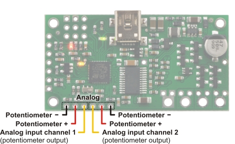 |
Simple Motor Controller 18v7 analog connections. |
|---|
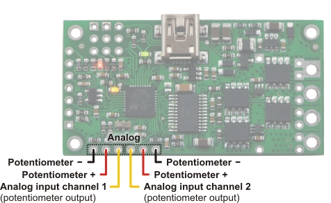 |
Simple High-Power Motor Controller 18v15 or 24v12 analog connections. |
|---|
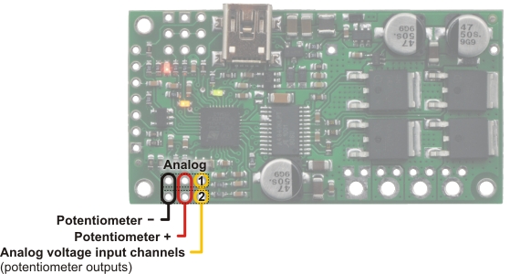 |
Simple High-Power Motor Controller 18v25 or 24v23 analog connections. |
|---|
Analog Connections Overview
The analog connection block consists of two channels. Each channel has a signal pin and a + and – pin for powering the analog voltage source. These potentiometer power pins are special in that they allow the Simple Motor Controller to detect if an analog channel has become disconnected, so we recommend using these pins rather than alternate power supplies or other pins on the board.
If you use an analog voltage source that is not powered from the Simple Motor Controller’s potentiometer power (+ and –) pins, you will need to check the Ignore Pot Disconnect checkbox under the Advanced Settings tab of the Simple Motor Control Center (see Section 5.3).
We recommend using a potentiometer in the 1 kΩ to 10 kΩ range. Higher-resistance potentiometers will not work well with the potentiometer disconnection detection feature. If you need to use a higher-resistance potentiometer, you can disable potentiometer disconnection detection from the Simple Motor Control Center.
Note: The analog channel inputs are not 5V tolerant, so you must not connect voltages over 3.3 V to these pins. If your control source outputs voltages higher than 3.3 V, you can use a voltage divider to ensure the voltage is always at an acceptable level.
The channel pins have a 0.1" spacing, which means that a female-female servo extension cable can be used to connect a potentiometer or analog joystick to the motor controller board.
Simple Wiring Example: Connecting to a Potentiometer
 |
Wiring diagram for connecting a potentiometer or joystick to a Simple Motor Controller. |
|---|
Using the Analog Channels
The Simple Motor Controller is constantly sampling the two analog channels and making the measured voltages available via the USB and serial interfaces, even when the controller is not in analog mode. For example, you can use the serial interface to read the analog channel values while the motor controller is in RC mode. The analog channels are read with 12-bit (0.8 mV) resolution.
Driving a Motor
In analog mode, the channel values are mapped to motor speed based the channel calibration values and the mixing mode. We recommend your first step after connecting your analog voltage source be to use Quick Input Setup Wizard in the Simple Motor Control Center. The wizard instructs you to move your inputs to their extremes and maps one extreme to the maximum forward motor speed, the neutral position to speed zero, and the other extreme to maximum reverse speed. Calibration can have a significant impact on performance.
If mixing mode is disabled, only channel 1 affects motor speed. If mixing mode is set to “right” or “left”, channel 1 is considered the “throttle” input and channel 2 is considered the “steering” input. Left mixing mode obtains motor speed by summing the throttle and steering channels (CH1+CH2) while right mixing mode obtains motor speed by taking the difference of the throttle and steering channels (CH1-CH2). To see why this makes sense, consider a differential-drive robot (a robot with a motor on each side) with a left motor driven by a Simple Motor Controller in left mixing mode and a right motor driven by a Simple Motor Controller in right mixing mode. When throttle is full forward (CH1=max) and steering is neutral (CH2=0), left- and right-mixed motors are both driven forward at full speed and the robot goes forward. When throttle is neutral (CH1=0) and steering is full right (CH2=max), the left mixing results in motor forward at full speed while right mixing results in motor reverse at full speed, so the robot turns right.
As demonstrated above, using both analog channels in mixing mode makes it possible to combine two joystick-controlled Simple Motor Controllers to achieve single-stick (mixed) control of a differential drive robot. The connection diagram for such a setup would be very similar to the RC-mixing diagram shown in Section 4.3.
Limit/Kill Switches
Unused analog channels can also be used as limit or kill switches. When configured as a limit or kill switch, if the channel value exceeds more than half of its “forward” value, the switch is activated. If you want to use a push-button switch for this purpose, we recommend using a normally closed (NC) switch connected in one of the two ways depicted in the diagrams below:
|
|
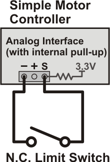
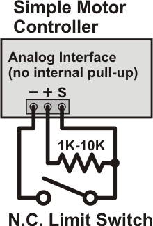
By using a normally closed limit switch, you ensure that if the switch becomes disconnected in some way, the controller considers the limit/kill switch active and stops the motor. The left wiring diagram is simpler because it uses an internal pull-up resistor (enabled using the Simple Motor Control Center), but it can only result in one of two possible states: switch active or switch inactive. The right wiring diagram above is able to take advantage of the potentiometer disconnection detection feature. Pressing the switch activates it, releasing it deactivates it, and disconnecting it results in a disconnection error or an activated switch, depending on which parts of the switch are disconnected.
The above configurations should work with the default analog channel calibration values, but we still recommend you use the Channel Setup Wizard (click the “Learn…” button in the Simple Motor Control Center) for any analog channel you configure as a limit or kill switch.
Normally open (NO) switches can also be used as limit/kill switches with this controller, but they are not as safe since accidental disconnection will lock the switch in an inactive state.
Related products


Home | Forum | Blog | Support | Ordering Information | Lists | Distributors | BIG Order Form | About | Contact
© 2001–2026 Pololu Corporation
