Support » Pololu Maestro Servo Controller User’s Guide » 4. Using the Maestro Control Center »
4.b. Channel Settings
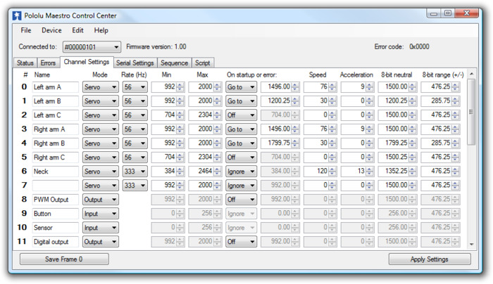 |
The Channel Settings tab in the Maestro Control Center. |
|---|
The Channel Settings tab contains controls for many of the channel-related parameters that are stored on the Maestro, affecting its operation immediately on start-up.
A separate row of controls is displayed for each of the Maestro’s channels:
Name. Each of the channels may be assigned a name, for your convenience. Channel names are not stored on the device but instead in the system registry on your computer; if you want to use your Maestro on a different computer without losing the names, save a settings file on the old computer and load it into the Maestro with the new one.
Mode. The mode of the channel is the most basic setting determining its operation. There are three options:
- Servo (the default) indicates an R/C servo PWM output.
- Input specifies that the channel should be used as an analog or digital input. The inputs on channels 0–11 are analog: they are measured continuously as a value between 0 and 1023 (VCC), at a maximum rate of about 20 kHz. The inputs on channels 12–23 are digital: their values are either exactly 0 or exactly 1023. Note that the values displayed in the Target and Position boxes in the Status tab are one quarter of the actual input value, so 1023 is displayed as 255.75.
- Output specifies that the channel should be used as a simple digital output. Instead of indicating a pulse width, the position value of the channel is used to control whether the output is low (0 V) or high (VCC). Specifically, the output is low unless the position value is greater than or equal to 1500.00 μs.
Rate specifies the pulse rate for each Servo channel. On the Micro Maestro 6, all servos must have the same pulse rate, while on the Mini Maestro 12, 18, an 24, you can have two different rates and choose which rate to use on each channel. The pulse rates available are controlled by the Period and Period multiplier settings described below.
Min and Max specify the allowed values for the channel’s position. For channels configured as Servo outputs, the Min and Max settings correspond respectively to the minimum and maximum allowed pulse widths for the servo, in units of microseconds.
On startup or error. This option specifies what value the target of the channel should have when the device starts up (power-up or reset) or when there is an error. Note that if there is a speed or acceleration setting for the channel, the output will smoothly transition to the specified position on an error, but not during start-up, since it has no information about the previous position of the servo in this case.
- Off specifies that the servo should initially be off (have a value of 0), and that it should be turned off whenever an error occurs.
- Ignore specifies that the servo should initially be off, but that its value should not change on error.
- Go to specifies a default position for the servo. The servo target will be set to this position on start-up or when an error occurs.
Speed. This option specifies the speed of the servo in units of 0.25 μs / (10 ms). For example, with a speed of 4, the position will change by at most 1 μs per 10 ms, or 100.00 μs/s. Mini Maestro 12, 18, and 24 only: If you use a period other than the default 20 ms, the units of speed are different. See below for more information.
Acceleration. This option specifies the acceleration of the servo in units of (0.25 μs) / (10 ms) / (80 ms). For example, with an acceleration of 4, the speed of the servo will change by a maximum of 1250 μs/s every second. Mini Maestro 12, 18, and 24 only: If you use a period other than the default 20 ms, the units of acceleration are different. See below for more information.
8-bit neutral. This option specifies the target value, in microseconds, that corresponds to 127 (neutral) for 8-bit commands.
8-bit range. This option specifies the range of target values accesible with 8-bit commands. An 8-bit value of 0 results in a target of neutral – range, while an 8-bit value of 254 results in a target value of neutral + range.
Advanced pulse control options are available:
Period is an advanced option that sets the period of all of the servo pulses, in milliseconds. This is the amount of time between successive pulses on a given channel. If you are unsure about this option, leave it at the default of 20 ms. Mini Maestro 12, 18, and 24 only: the units of speed and acceleration depend on the pulse rate. The units depend only on Period, not on Period multiplier. Please refer to the following table for the relationship between Period and speed/acceleration units:
| Period (T) | Rate | Speed units | Acceleration units |
|---|---|---|---|
| T = 20 ms | 50 Hz | (0.25 μs)/(10 ms) | (0.25 μs)/(10 ms)/(80 ms) |
| T = 3–19 ms | > 50 Hz | (0.25 μs)/T | (0.25 μs)/T/(8T) |
| T > 20 ms | < 50 Hz | (0.25 μs)/(T/2) | (0.25 μs)/(T/2)/(4T) |
Servos available is an advanced option for the Micro Maestro only specifying the number of channels that may be used to control servos. For example, if this value is set to 4, only the channels 0–3 will be available as servo channels. The other channels must all be set to Input or Output. The only reasons to make fewer servos available are to allow a longer maximum pulse length or a shorter period.
Period multiplier is an advanced option for the Mini Maestro 12, 18, and 24 that allows a larger period (lower pulse rate) on some of the channels. For example, if you select a period of 3 and a multiplier of 6, you can have some servos run at 3 ms (333 Hz) and the others at 18 ms (55 Hz). When the multiplier is greater than 1, the pulse rate options will be shown in each channel in the Rate column.
For the Mini Maestro 24-channel servo controller, one extra option is available:
Enable pull-ups on channels 18-20 turns on pull-up resistors for all of the channels 18-20 that are configured as inputs. This guarantees that the input value will be high when nothing else is driving the line. When enabled, this feature allows you to connect buttons or switches to channels 18, 19, or 20 without supplying your own external pull-up resistor: simply connect the button/switch between ground and signal line.
Related products


Home | Forum | Blog | Support | Ordering Information | Lists | Distributors | BIG Order Form | About | Contact
© 2001–2026 Pololu Corporation
