Support » Understanding Destructive LC Voltage Spikes »
5. Limiting the Magnitude of the LC Spikes
There are several ways to limit the magnitude of the initial LC transients we’ve seen so far:
- Limit lead inductance
- Add resistance to the LC circuit
- Add a large, high-ESR capacitor across (in parallel with) the low ESR capacitor
Limiting Inductance
Reducing lead inductance is an obvious way to mitigate the problem caused by lead inductance. The primary way to reduce the inductance is to use shorter, thicker wires. This might not always be practical, but limiting LC transients is just one of several good reasons for avoiding excessively long wires in your designs (others include limiting resistance and reducing noise generation or susceptibility).
With the same power switch used earlier but with a battery and shorter leads we see the result is slightly improved:
 |
Oscilloscope capture of the voltage (yellow) and current (green) when using a battery with short leads. |
|---|
The charged battery voltage is over 13 V, so the 25 V peak we see here is now less than double the voltage we’re intending to apply. It could still destroy some components, but there are many more that can survive 25 V than can survive 40 V.
Adding Series Resistance
Unfortunately, we’re still left with a potentially destructive transient, and in cases such as the bench power supply, reducing lead length can be impossible or very inconvenient. The next thing we can consider is adding resistance in series with the power leads to limit the initial current surge. In low-power applications, even several ohms of resistance might be tolerable since the resulting voltage and power loss under typical conditions might be negligible.
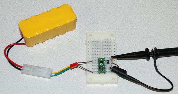
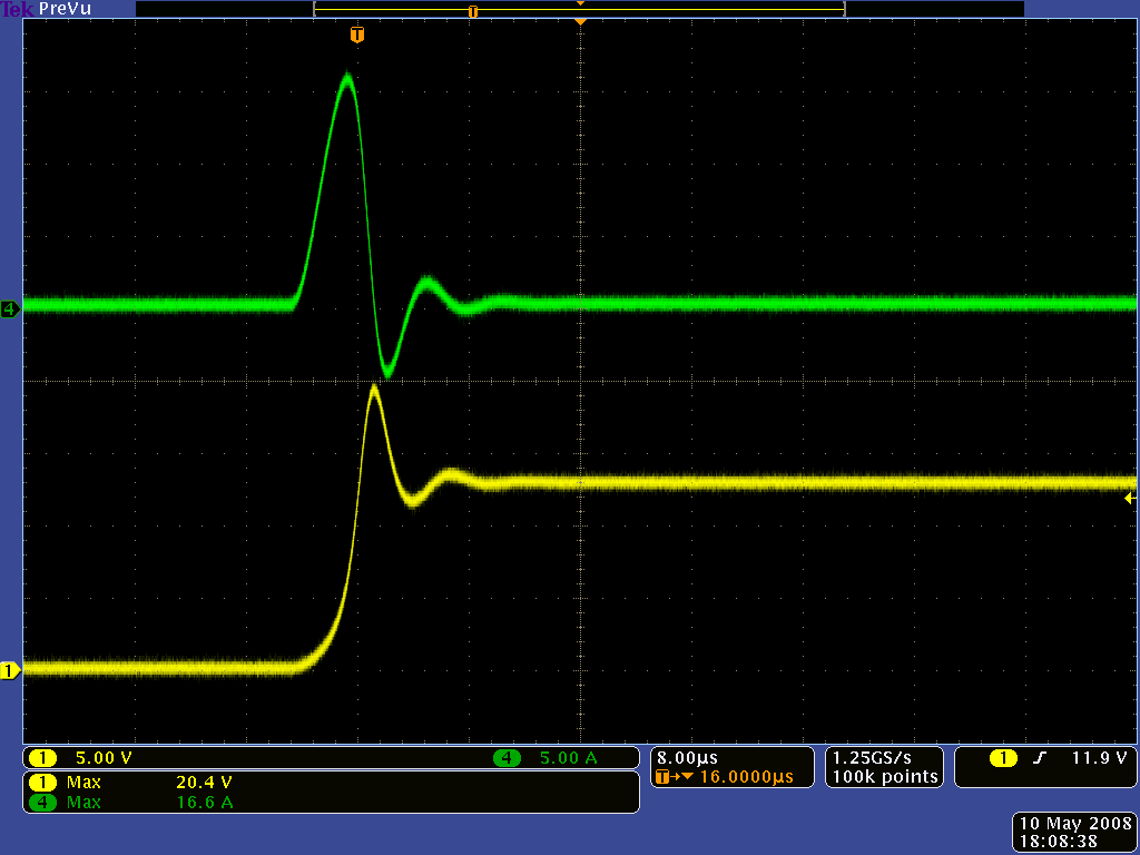
However, adding resistance can be very undesirable in high-power applications. One option in such cases is to replace the instantaneous connection of a mechanical switch with the more gradual transition offered by an electronic switch, such as a MOSFET. We tested this approach with the Pololu pushbutton power switch, which is based on a MOSFET:
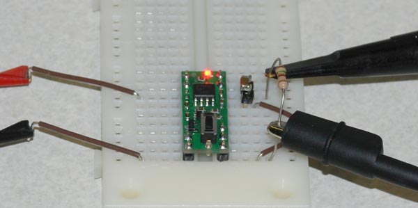 |
LC spike test setup close-up showing Pololu pushbutton power switch. |
|---|
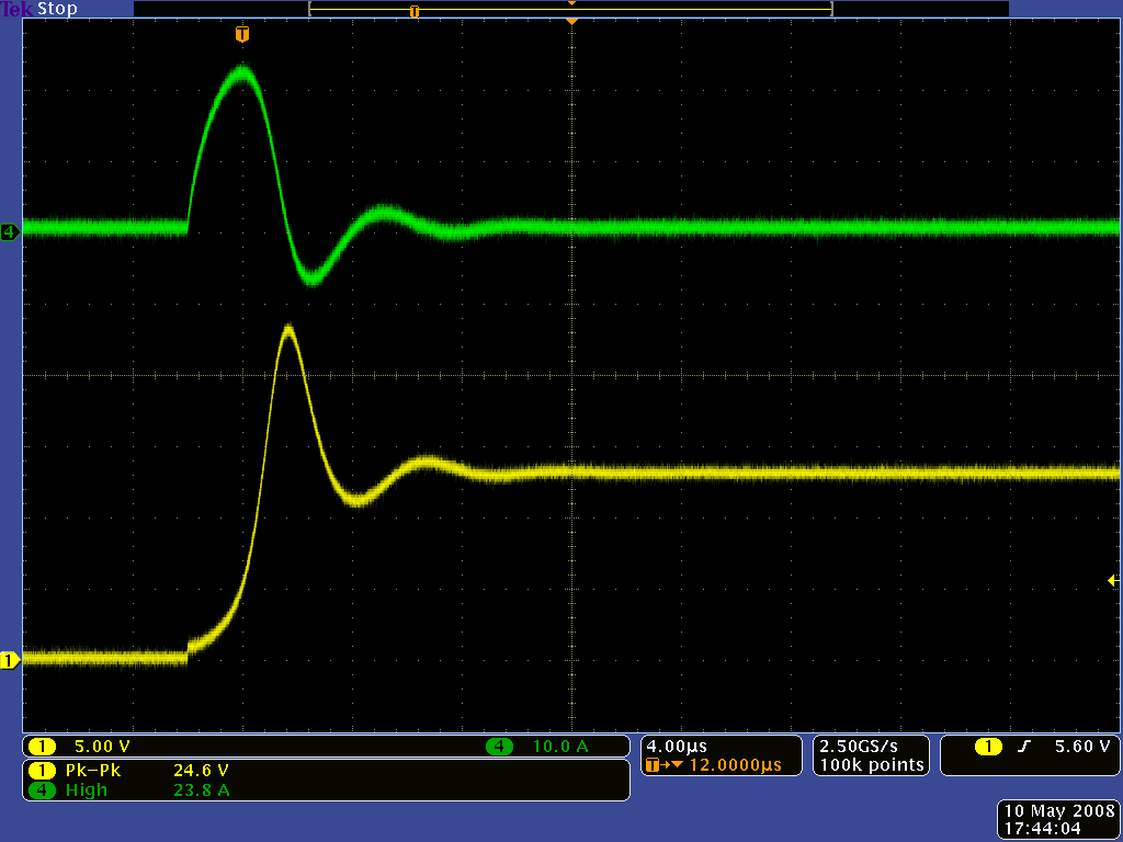
The MOSFET does add a bit of resistance (typically around 0.01 ohms), but the important factor is the MOSFET’s gradual transition from non-conductive to conductive. With the mechanical switch replaced by a MOSFET, the 40-volt peak we saw was reduced to under 20 V:
 |
Oscilloscope capture of voltage (yellow) and current (green) when using the Pololu pushbutton power switch and bench power supply. |
|---|
It’s worth noting that the circuit in the Pololu pushbutton power switch is not especially designed to turn on slowly, so an electronic-switch approach could completely eliminate the transient with a slower turn-on time. In the case of the Pololu pushbutton power switch, double-clicking quickly enough when starting in the on state (i.e. turning off and immediately turning back on) can cause the second turn on to be faster, leading to results more similar to those with the mechanical switch:
 |
Oscilloscope capture of voltage (yellow) and current (green) when “double-clicking” a Pololu pushbutton power switch connected to a bench power supply. |
|---|
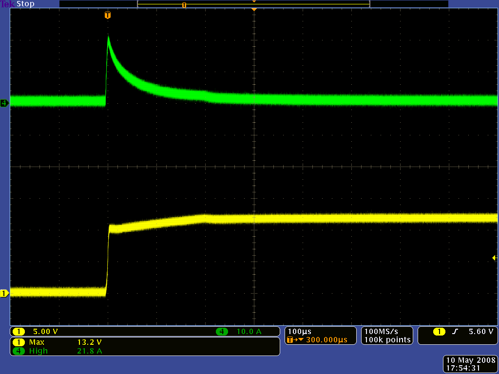
We then combined the MOSFET-based approach with the reduced wire inductance of the battery test:
 |
LC spike test setup with battery pack and Pololu pushbutton power switch. |
|---|
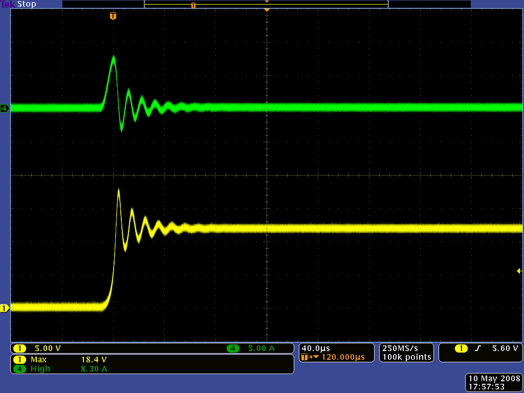
After seeing so many spikes, the near perfection of the transition is quite refreshing:
 |
Oscilloscope capture of voltage (yellow) and current (green) when using the Pololu pushbutton power switch and a battery. |
|---|
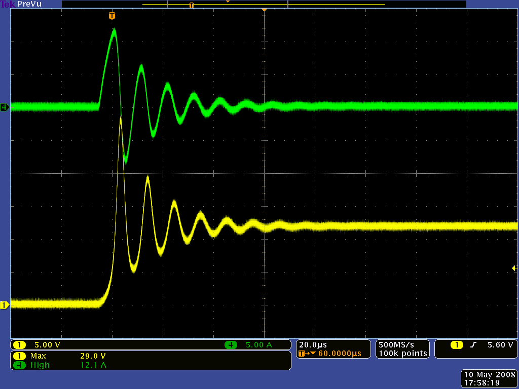
In the case of the Pololu pushbutton power switch, there is still the unfortunate (in this application) double-click possibility: after many attempts at getting the right timing, we were still able to catch some spikes, though they were much less severe than the 40 V peaks we saw earlier:
 |
Oscilloscope capture of voltage (yellow) and current (green) when “double-clicking” a Pololu pushbutton power switch connected to a battery. |
|---|
Adding a Large, High-ESR Capacitor
We introduced the LC transient problem as being unique to ceramic capacitors with low equivalent series resistance (ESR). One particularly straightforward solution to the problem is to add a large capacitor with high ESR to the circuit. The large capacitor prevents the voltage from changing quite as quickly, yet its high ESR prevents it from drawing as much initial current. Here is the result when we added a 100 uF electrolytic capacitor in parallel with our 10 uF test capacitor:
 |
Oscilloscope capture of voltage (yellow) and current (green) when a 100 uF electrolytic capacitor is added in parallel with the ceramic capacitor. |
|---|
So, why not always use the large capacitor? When working on a large breadboard with a large power supply, there is little reason not to. However, in space-constrained applications, the capacitor might not be an option: one of the main appeals of the ceramic capacitor is its small size, and the necessary capacitor (it must have much higher capacitance and it cannot be the compact ceramic) might be larger than the rest of the circuit. It might also take some experimenting to determine the input capacitance of an unknown device and to see which external capacitors have the right ESR.
Related products


Home | Forum | Blog | Support | Ordering Information | Lists | Distributors | BIG Order Form | About | Contact
© 2001–2026 Pololu Corporation
