Micro gripper with position feedback servo
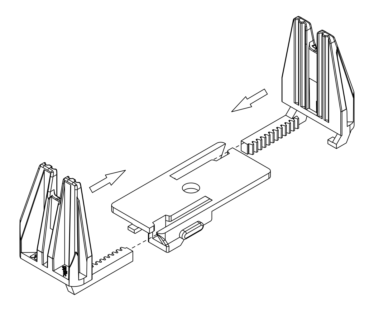
- Slide the two gripper paddles into the slots on the gripper plate and push them together until they meet at the center.
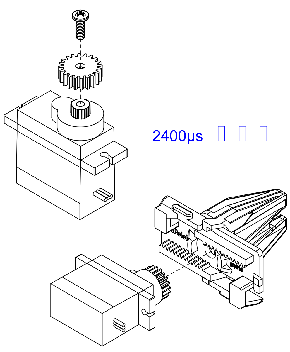
- Install the gripper pinion gear on the micro servo using the included screw and use your servo controller to command the servo to the fully closed position (2400 µs pulse duration). Holding the gripper paddles together, insert the pinion gear between the paddles, making sure the servo is in the orientation as shown.
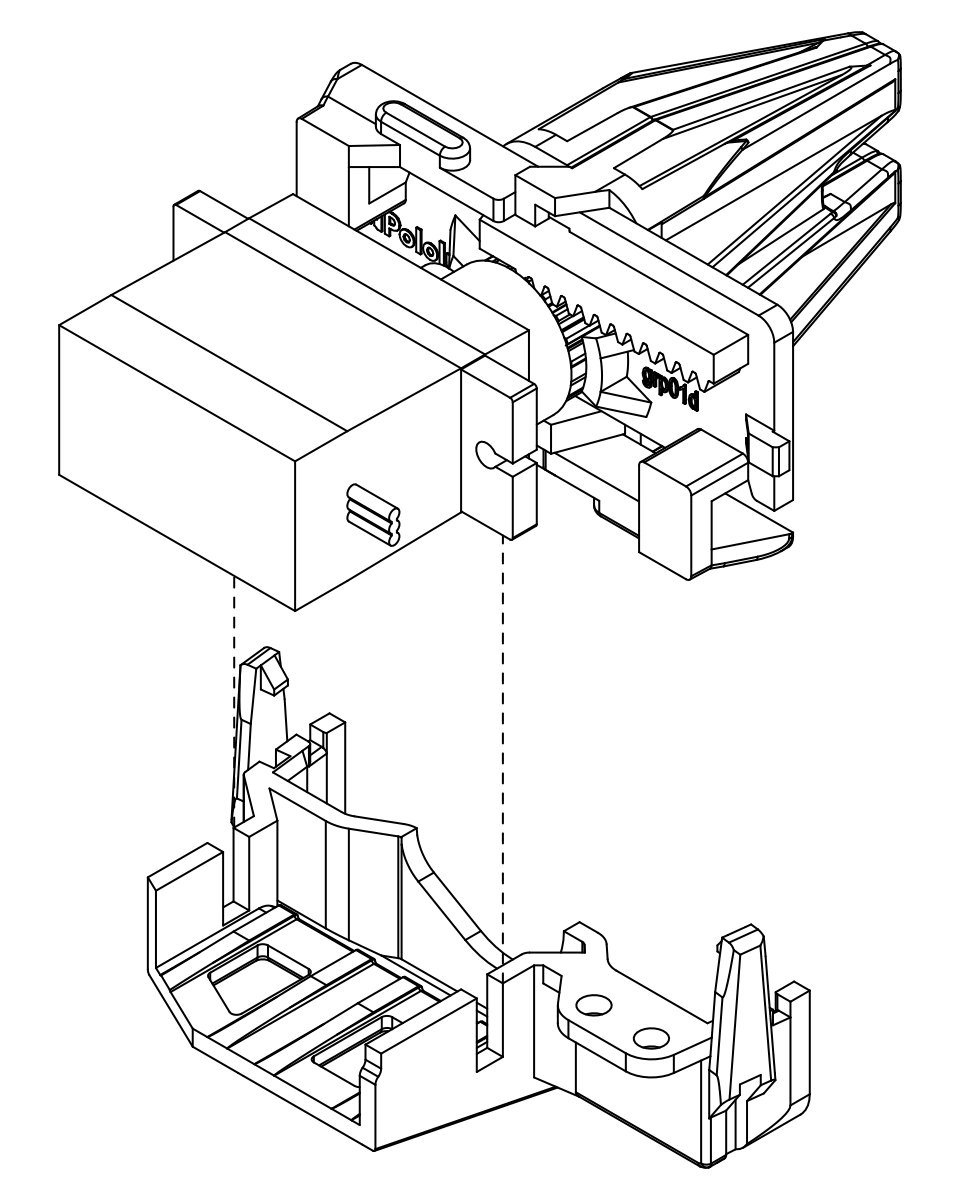
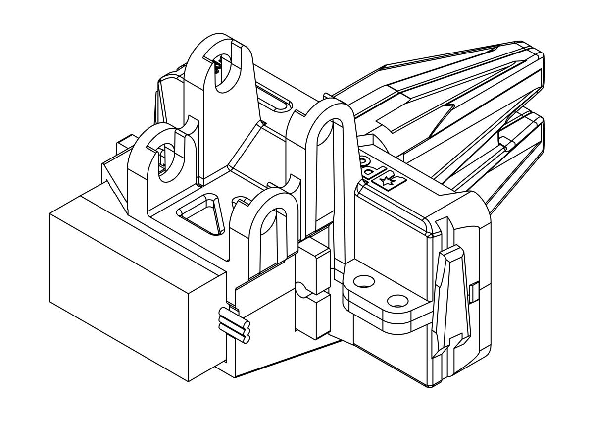
- Keeping the paddles and servo in place, slide the assembly into the bottom micro gripper case.
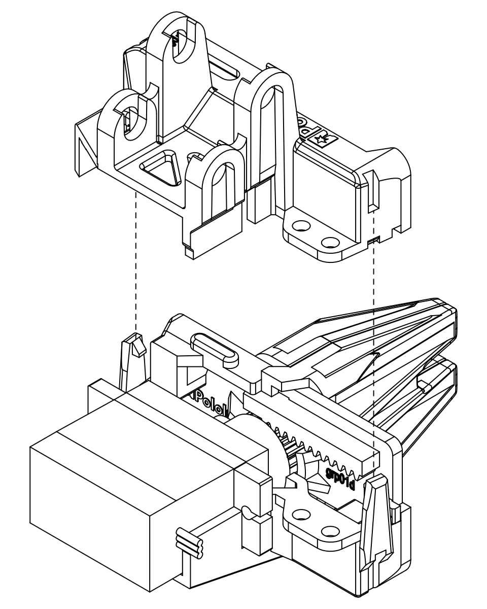
- Align the top micro gripper case with the bottom micro gripper case and press them together, ensuring the clips snap closed.
Your gripper subassembly is now complete! If you ever need to open the micro gripper case. you can gently lift on the clips and pull them apart. A small screwdriver can help get under the clip. Set it aside for now; you will attach it to the end of the arm once it is assembled.
Robot Arm Kit for Romi assembly
Do not overtighten screws. The screws used in the joints of the arm should be firmly tightened, but not enough to deform the nylon spacers. Overtightening the screws can increase the friction in the joints and result in much higher loads on your servos, potentially leading to damage.
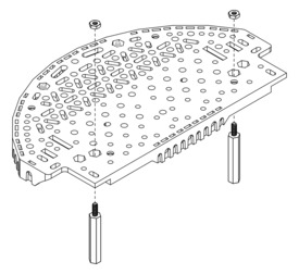
- Since the servos will be mounted on top of the mounting holes for the standoffs, install the standoffs on the Romi expansion platform first. Start by putting the #2 nuts in the hexagonal holes shown below, and threading them onto the 1.5″ aluminum standoffs inserted through the mounting hole in the Romi expansion platform.
- Do the same for the 1″ standoffs on the front of the platform. Note that you should be using the two mounting holes closer to the center of the chassis.
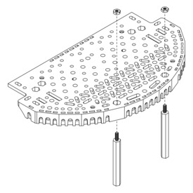 | Installing 1.5″ aluminum standoffs on the Romi expansion platform. |
|---|
|
 | Installing 1″ aluminum standoffs on the Romi expansion platform. |
|---|
|
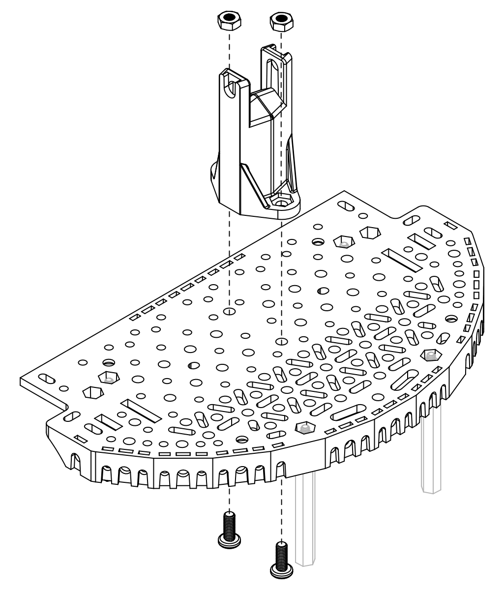
- Next, install the pivot stand onto the Romi expansion platform using two 8 mm M3 screws and M3 nuts. The nuts should be seated into the cut-outs in the base of the stand.
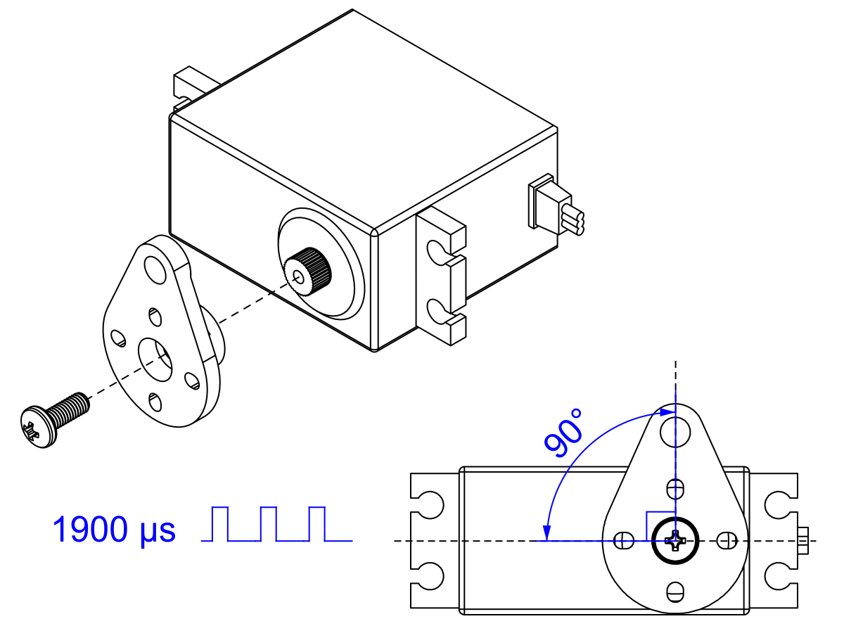
- Prepare the lift servo by using your servo controller to command it to move to the proper starting position (1900 µs pulse duration) and install the lift servo horn (the shorter of the two) with the included mounting screw so it forms a 90° angle to the body of the servo, as shown.
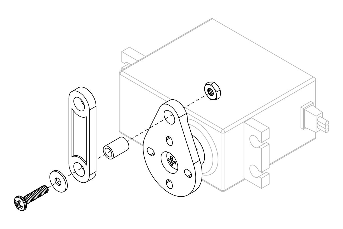
- While the servo is easily accessible, now is a good time to install the short linkage on the lift servo horn. Start by aligning the linkage and inserting a 6 mm nylon spacer through the hole on both parts. Then, insert a 3/8″ #2-56 screw with a washer through the spacer and secure it with a #2 nut on the other side. All of the joints on the arm will use this same method (with appropriately sized screws and nylon spacers).
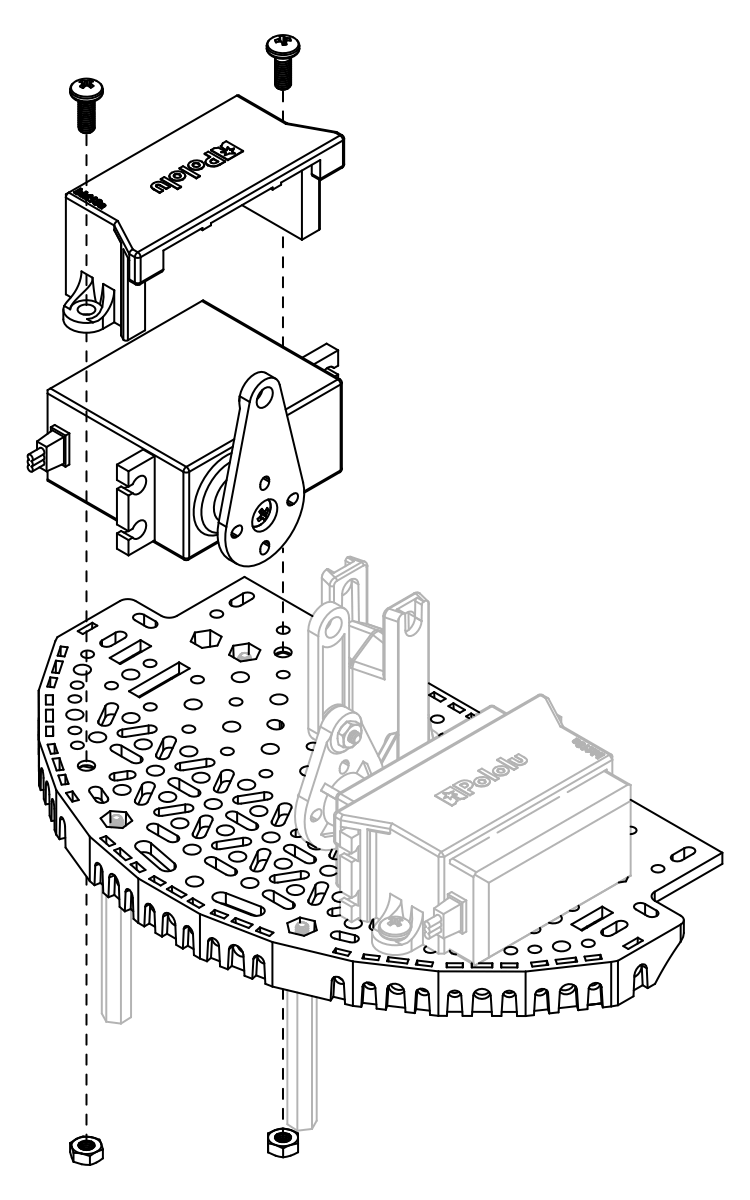
- Use one of the servo mounting brackets to secure the lift servo to the right side of the Romi expansion platform using two 8 mm M3 screws and M3 nuts. The nuts should seat into the cutouts on the underside of the Romi expansion platform.
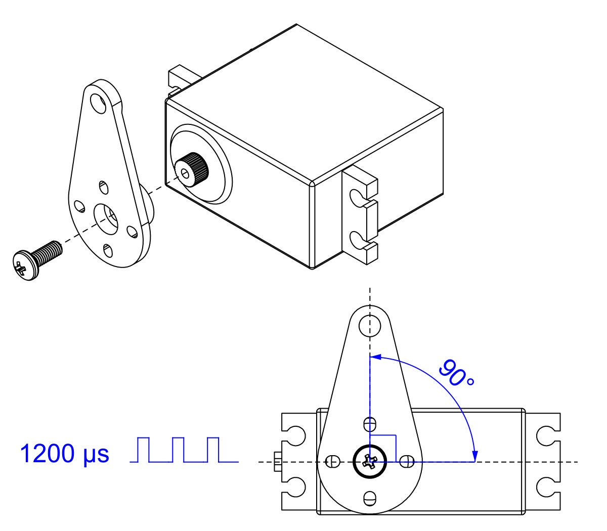
- Prepare the tilt servo by using your servo controller to command it to move to its starting position (1200 µs pulse duration), then install the tilt servo horn with the included mounting screw, making sure it is aligned as shown.
- Use the other servo mounting bracket to secure the tilt servo to the left side of the Romi expansion platform, again using two 8 mm M3 screws and M3 nuts.
- Use a 20 mm nylon spacer, 1″ #2-56 screw, a washer, and a #2 nut to install the main arm to the pivot stand as shown.
- Connect the main arm to the lift servo linkage using a 6 mm nylon spacer, 3/8″ #2-56 screw, washer, and #2 nut as shown.
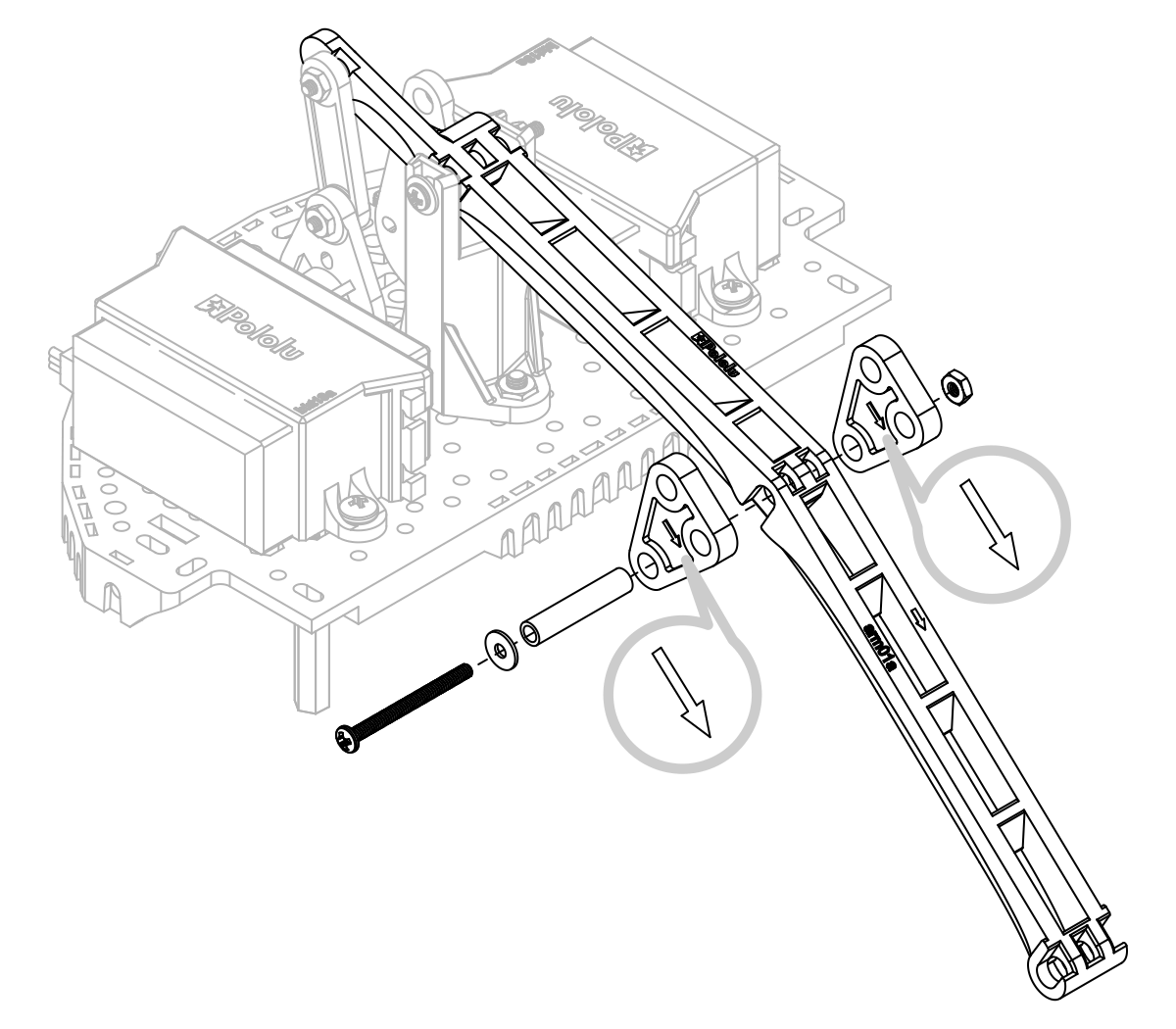
- The next step is to install the two triangular pivot transfer linkages, one on either side of the main arm, making sure the direction indicator arrows are facing forward. Use a 20 mm nylon spacer, 1″ #2-56 screw, a washer, and a #2 nut to secure the 3 components together using the bottom-most hole in the triangular pivot transfer linkages.
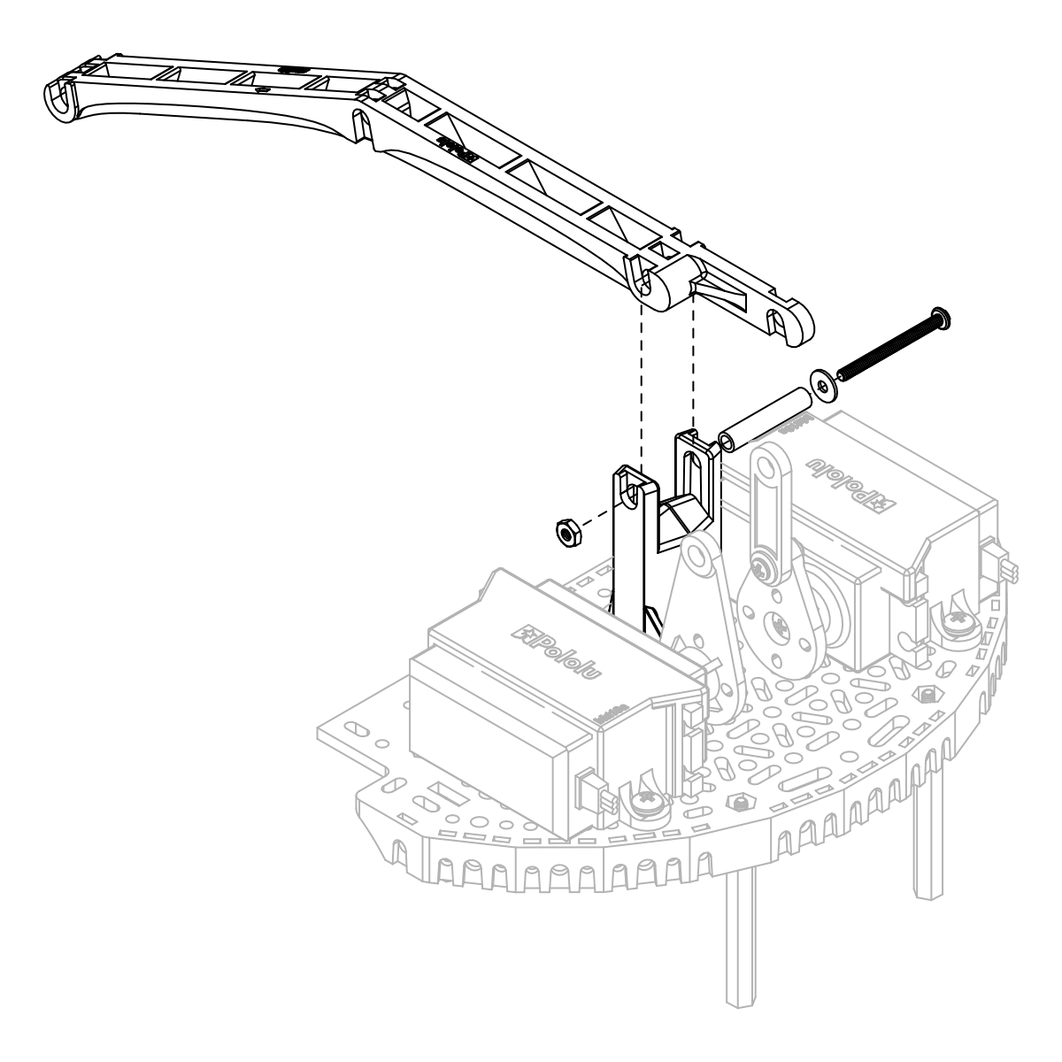
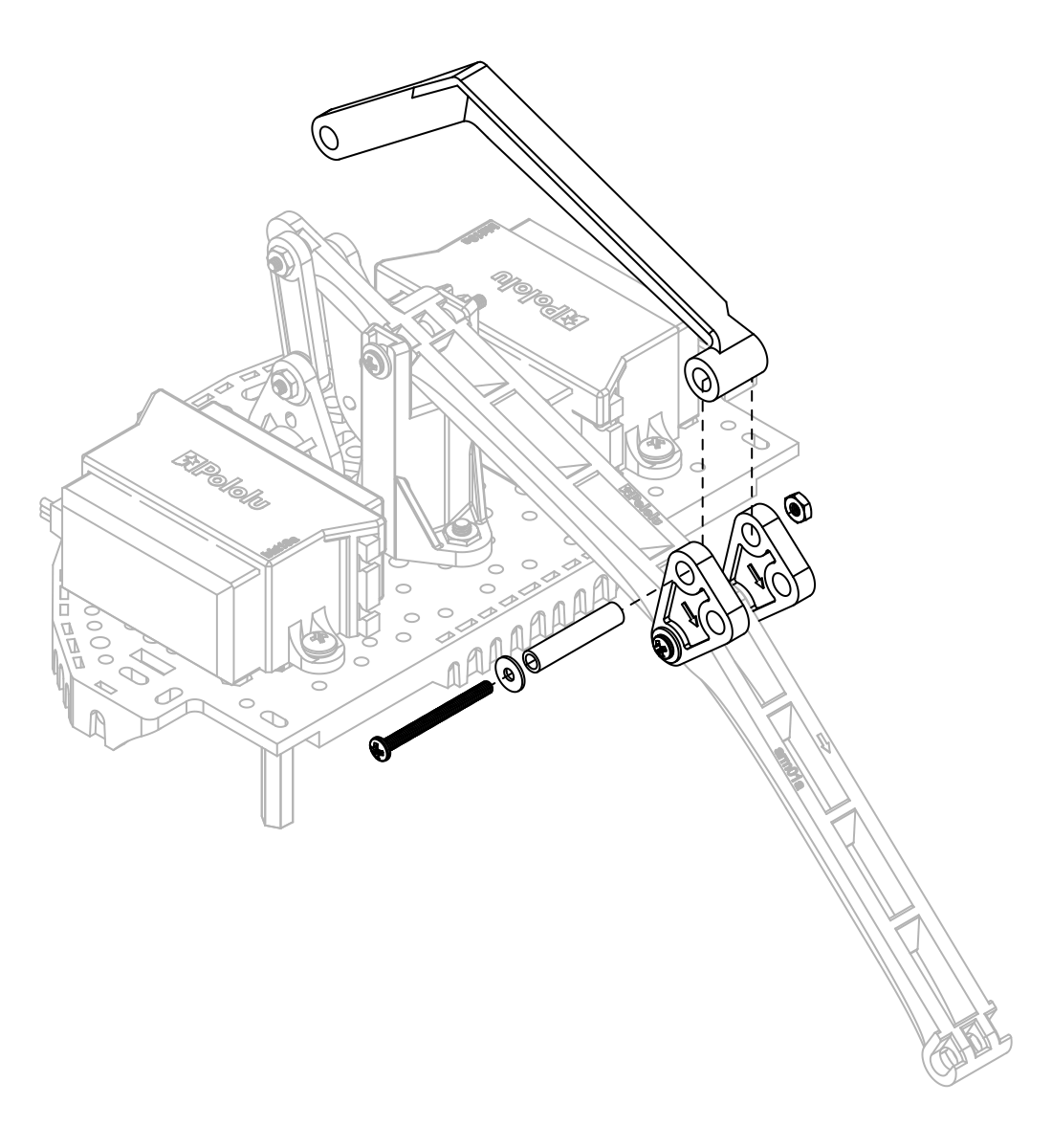
- Connect the rear tilt arm to the top of the triangular pivot transfer linkages (again using a 20 mm nylon spacer, 1″ #2-56 screw, a washer, and a #2 nut). Then, secure the other side of the rear tilt arm to the tilt servo horn using a 6 mm nylon spacer, 3/8″ #2-56 screw, washer, and #2 nut.
 | Installing the rear tilt arm on the Robot Arm for Romi accessory. |
|---|
|
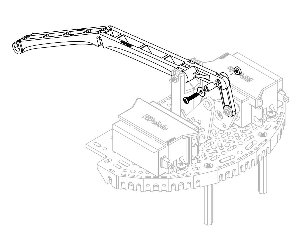
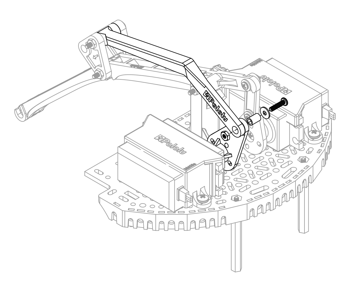
 | Connecting the rear tilt arm to the tilt servo on the Robot Arm for Romi accessory. |
|---|
|
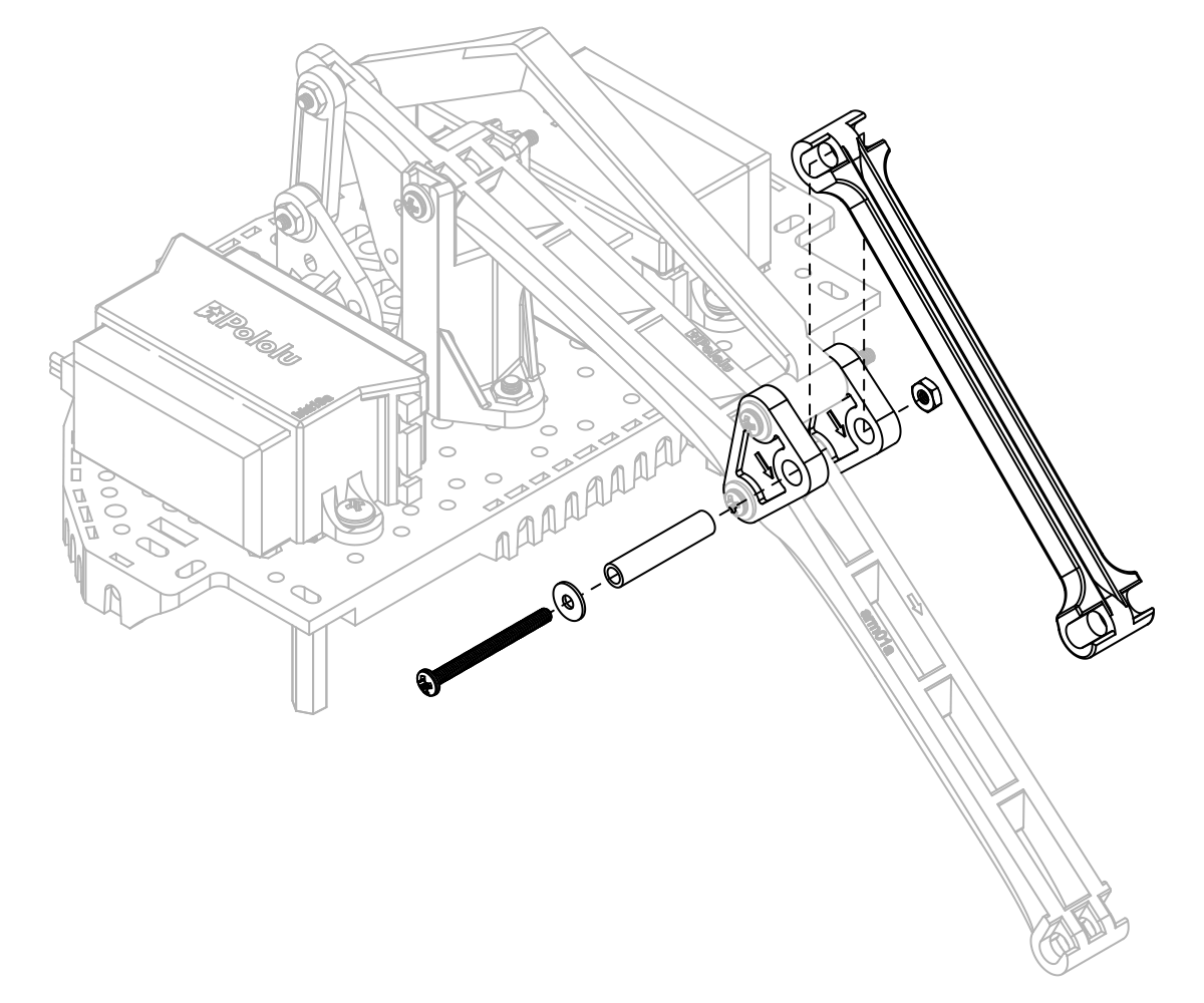
- Using a 20 mm nylon spacer, 1″ #2-56 screw, a washer, and a #2 nut, connect the front tilt arm to the last available mounting holes on the triangular pivot transfer linkages, ensuring the direction indicator arrow on the underside of the front tilt arm is pointing forward.
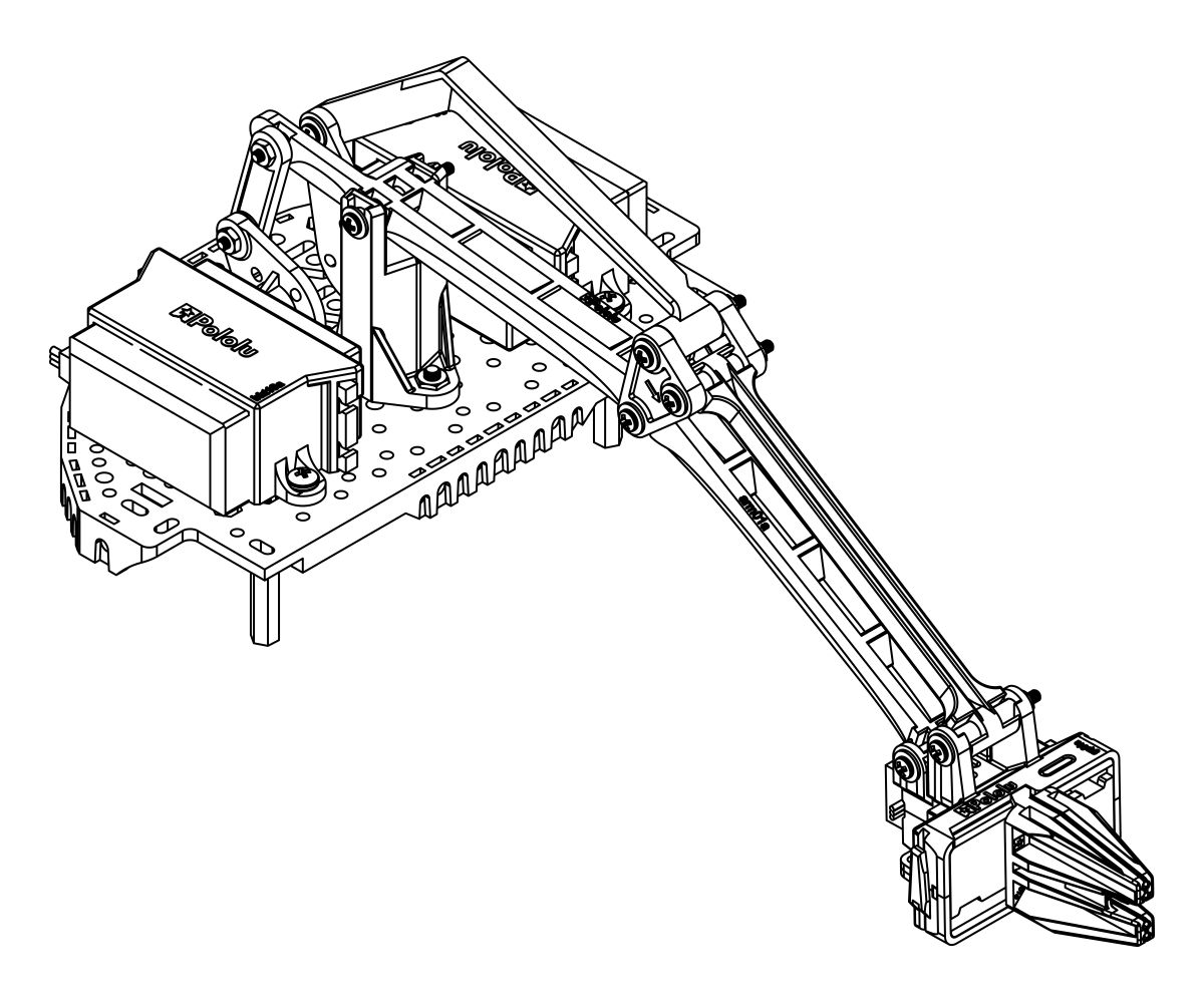
- Attach the completed gripper sub-assembly to the end of the arm using a 20 mm nylon spacer, 1″ #2-56 screw, a washer, and a #2 nut for each joint. To keep the servo wires tidy, you can snake them back along the main arm through the holes down the spine.
The assembly of your Robot Arm Kit for the Romi is now complete!
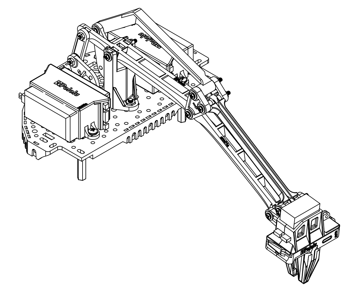
The micro gripper can also be flipped around and used in an alternative orientation as shown below.
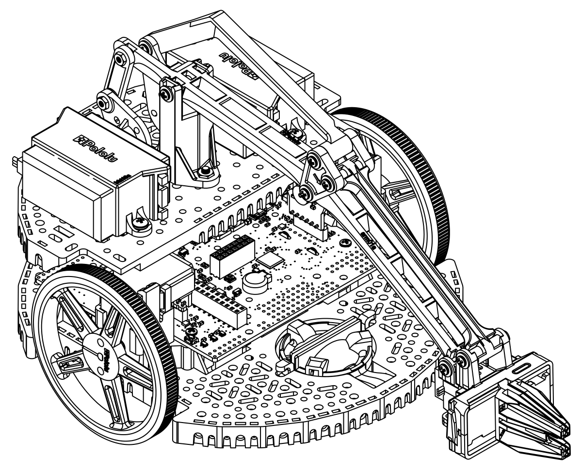
To install the arm accessory on the Romi chassis, align the rear aluminum standoffs with the mounting holes on the rear of the Romi Chassis. and the aluminum standoffs on the front of the arm assembly to the mounting holes nearest to the motors on the Romi chassis, as shown. Insert a 1/4″ #2-56 screw through each mounting hole from the bottom of the chassis, threading it into the standoff above.
The Robot Arm accessory is now installed on the Romi chassis. You can tidy up the wiring for the gripper servo by running the wires along the main arm, passing the wire through the openings along the way, just be sure to leave the servo enough wire to accommodate the gripper’s full range of motion. Additionally, the two rear-most slots on the Romi expansion plate are large enough to pass the servo wires through so they can be routed down to the first level without leaving the profile of the chassis.
Note: Lifting an object will generally cause the Romi to tilt forward, so we highly recommend using the optional second ball caster attachment. The front ball caster is supported by a flexible arm that acts as a suspension system. You can wrap a rubber band around the two hooks located on either side of the ball caster on the top side of the chassis to increase the stiffness of the suspension and help keep the robot stable.