Support » Jrk G2 Motor Controller User’s Guide » 7. Details »
7.6. Motor settings
The Jrk’s motor settings consist of parameters that determine how its duty cycle target is converted to a duty cycle and how the duty cycle corresponds to motor outputs, together with parameters that control its current sensing and limiting behavior. These settings can be configured on the Motor tab of the Jrk G2 Configuration Utility.
PWM frequency
The Jrk is capable of both 20 kHz and 5 kHz PWM, selectable with the “PWM frequency” setting.
The 20 kHz PWM frequency is ultrasonic and can thus eliminate audible PWM-induced motor humming, which makes this frequency desirable for typical applications.
However, a higher PWM frequency means greater power loss due to switching (producing more heat), which could make a 5 kHz PWM frequency a better choice for certain applications.
Additionally, the 5 kHz PWM frequency allows for slightly finer control at duty cycles approaching 0%. This is because PWM control pulses that are shorter than a certain time (about 4 µs for the Jrk G2 21v3 and 0.5 µs for the Jrk G2 18v19, 24v13, 18v27, and 24v21) have no effect on the output voltage.
Invert motor direction
The Jrk’s PWM duty cycle has a range of −600 to 600, where −600 is full reverse and 600 is full forward. In analog feedback mode, “forward” and “reverse” should be consistent with the scaled feedback values, so that when the duty cycle is positive, the motor spins in a direction that increases the scaled feedback. By default, full forward (+600) means motor output OUTA = VIN and OUTB = 0 V, while full reverse (−600) means OUTA = 0 V and OUTB = VIN. When checked, the “Invert motor direction” option switches these definitions so that full forward (+600) means OUTA = 0 V and OUTB = VIN, while full reverse (−600) means OUTA = VIN and OUTB = 0 V.
The feedback setup wizard can help you detect whether the motor direction needs to be inverted. It can be started by clicking the “Feedback setup wizard…” button next to the “Invert motor direction” checkbox when the feedback mode is analog. (This wizard can also be started from the Feedback tab.)
Motion parameters
Various limits may be applied to the duty cycle, each of which can be configured separately for forward (positive duty cycle) and reverse (negative duty cycle) if the “Asymmetric” option is checked:
“Max. duty cycle” limits the duty cycle itself.
“Max. acceleration” limits the amount that the duty cycle can increase in magnitude in a single PID period. For example, if there is a forward acceleration limit of 10, and the current duty cycle is 300, then the duty cycle in the next PID period can increase to no higher than 310.
“Max. deceleration” limits the amount that the duty cycle can decrease in magnitude in a single PID period. For example, if there is a forward deceleration limit of 10, and the current duty cycle is 300, then the duty cycle in the next PID period can decrease to no lower than 290.
“Brake duration” is a feature that is most useful for large motors with high-inertia loads used with frequency feedback or speed control mode (no feedback). If this option is used, the Jrk will automatically keep the motor at a duty cycle of 0 for the specified time when switching directions, after decelerating to 0 from the old direction but before beginning to accelerate in the new direction. (Note that if the “When motor is off” setting is set to “Coast”, the motor will coast instead of braking during this period.) The “forward” setting refers to switching from forward to reverse, and the “reverse” setting refers to switching from reverse to forward.
“Max. duty cycle while feedback is out of range” is an option to limit possible damage to systems by reducing the maximum duty cycle whenever the feedback value is beyond the absolute minimum and maximum values. This can be used, for example, to slowly bring a system back into its valid range of operation when it is dangerously near a mechanical limit. The “Feedback disconnect” error should be disabled when this option is used.
The “When motor is off” setting controls what the Jrk does with its motor outputs when the duty cycle is zero. There are two options: brake (OUTA and OUTB both connected to GND) or coast (OUTA and OUTB floating). With a non-zero duty cycle, the Jrk G2 PWMs the motor outputs between driving and braking.
You can familiarize yourself with motor coasting and braking using nothing more than a motor. First, with your motor disconnected from anything, try rotating the output shaft and note how easily it turns. Then hold the two motor leads together and try rotating the output shaft again. You should notice significantly more turning resistance while the leads are shorted together.
Current limiting and sensing
The motor driver circuit on the Jrk G2 allows it to monitor and limit the motor current. The measured current is reported on the Status tab of the configuration utility, and two different types of limits can be set on the Motor tab.
“Hard current limit" sets the hardware current limit for the Jrk’s motor driver circuit; when the motor current exceeds this value, the driver will actively limit it with current chopping. Hardware current limiting is performed entirely by the motor driver circuit, which means it can react quickly to current spikes (within a few microseconds) and is not dependent on the control loop running on the Jrk’s microcontroller. This setting is only available for the Jrk G2 18v19, 24v13, 18v27, and 24v21. The Jrk G2 21v3 has hardware current limiting with a fixed threshold of approximately 6.5 A, but the threshold decreases to 2.5 A when the motor driver temperature rises above approximately 160°C.
“Soft current limit" sets the motor current threshold for the “Soft overcurrent” error. If the Jrk’s motor current measurement exceeds this value, and the “Soft overcurrent” error is enabled, then the Jrk will set the corresponding error flag. See Section 7.7 for more information about error handling.
“Soft current regulation level" sets the target current level for software current regulation. If this setting is non-zero, then each PID period, the Jrk firmware will limit the duty cycle in an attempt to keep the measured current below this level. This feature generally works better when combined with acceleration and deceleration limits to help prevent rapid variations in duty cycle. This feature is only available on the Jrk G2 21v3, which does not have configurable hardware current limiting.
Note that the current limits are not precise thresholds: it is not unusual for the actual currents to be 20% off from the reported values, and currents near the lower end of each Jrk’s current capability are measured and limited less accurately. In addition, electrically noisy motors can cause the current measurement to be correspondingly unstable and inaccurate.
“Current samples” is the number of analog readings that the Jrk will perform and average together during each PID period in order to measure the current. A larger number of samples will tend to smooth out noise and current spikes better, but it takes more time and limits how fast the Jrk’s PID period can be.
“Hard overcurrent threshold” is the number of PID periods in which the motor current must be hardware-limited before the Jrk will report a “Hard overcurrent” error (if enabled). The default is 1, which means the Jrk will report an error after any detected occurrence of hardware current limiting, but you can raise this threshold to make the Jrk ignore shorter current spikes but still generate an error on longer ones. This setting is only available on the Jrk G2 18v19, 24v13, 18v27, and 24v21. The Jrk G2 21v3 cannot detect when hardware current-limiting occurs.
Current measurement on the Jrk G2 18v19, 24v13, 18v27, and 24v21
A high-power Jrk G2 (18v19, 24v13, 18v27, or 24v21) obtains a raw current sense measurement from the motor driver in the form of an analog voltage, which can be seen as the “Raw current” variable on the Status tab of the configuration utility and typically has an offset of about 50 mV when VIN is present, though the offset can vary widely from unit to unit. The Jrk converts this value into a current in units of milliamps with the following formulas (where the raw current sense measurement is Vraw and the reported current is I):
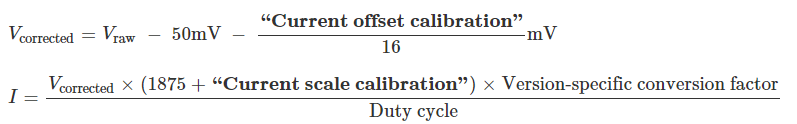 |
The two calibration settings adjust the results of this conversion: increasing the “Current offset calibration” shifts the reported current lower, and increasing the “Current scale calibration” scales the reported current larger.
If the Jrk reports extremely high, inaccurate currents while the motor is driving at a low duty cycle, it might be due to the analog current sense signal from the motor driver having an offset higher than the typical 50 mV offset. You can make the current readings more accurate at low duty cycles by setting the “Current offset calibration” setting properly.
Although setting the current limits appropriately can help protect the Jrk, your motor, and the rest of your system, please keep in mind that an over-temperature or over-current condition can still cause permanent damage; the higher-power Jrk G2 boards (18v19, 24v13, 18v27, and 24v21) do not have an over-temperature shut-off. (A motor driver error can indicate an over-temperature fault, but the higher-power Jrk G2s do not directly measure the temperature of the MOSFETs, which are usually the first components to overheat.)
Current measurement on the Jrk G2 21v3
The Jrk G2 21v3 obtains a raw current sense measurement from the motor driver in the form of an analog voltage, which be seen as the “Raw current” variable in the Status tab of the configuration utility. The Jrk converts this value into a current in units of milliamps with the following formulas (where the raw current sense measurement is Vraw and the reported current is I):
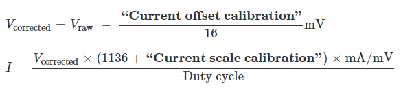 |
The two calibration settings adjust the results of this conversion: increasing the “Current offset calibration” shifts the reported current lower, and increasing the “Current scale calibration” scales the reported current larger.
Related products


Home | Forum | Blog | Support | Ordering Information | Lists | Distributors | BIG Order Form | About | Contact
© 2001–2026 Pololu Corporation
