Support » Jrk G2 Motor Controller User’s Guide » 4. Basic setup »
4.2. Connecting the motor and power supply
The information in this section can help you connect your motor and power supply to the Jrk G2.
Warning: This product is not designed to or certified for any particular high-voltage safety standard. Working with voltages above 30 V can be extremely dangerous and should only be attempted by qualified individuals with appropriate equipment and protective gear.
Warning: This product can get hot enough to burn you long before the chips overheat. Take care when handling this product and other components connected to it.
It is a good practice to check that things are working in small chunks, rather than doing your first checks after you have spent hours making a complicated system. Before connecting anything to the Jrk, we recommend connecting it to USB and running the Jrk G2 Configuration Utility, as described in Section 3.
Before connecting anything else, disconnect the Jrk from USB. Generally, rewiring anything while it is powered is asking for trouble.
You can solder the terminal blocks that come with the Jrk to the four large through-holes to make your motor and power connections, or you can solder an 8-pin piece of the 0.1″ header strip (which also comes with the Jrk) into the smaller through-holes that border these larger holes. Note, however, that the terminal blocks are only rated for 16 A, and each header pin pair is only rated for a combined 6 A, so for higher-power applications, we recommend soldering thick wires directly to the board. If you have a Jrk G2 21v3 with connectors already soldered, then you do not need to solder anything to the Jrk to make your motor and power connections.
|
|
||||
|
|
||||
|
|||||
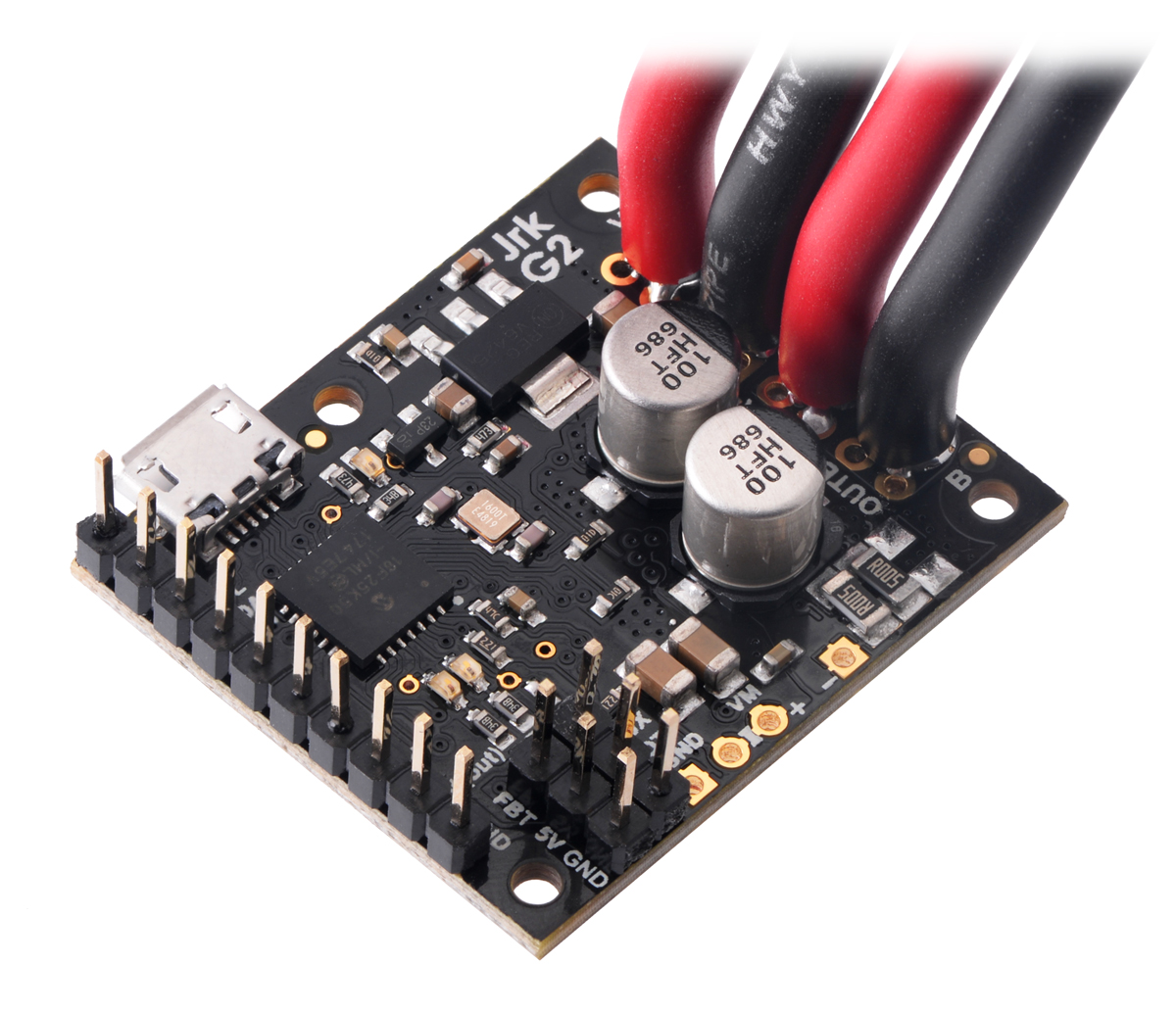
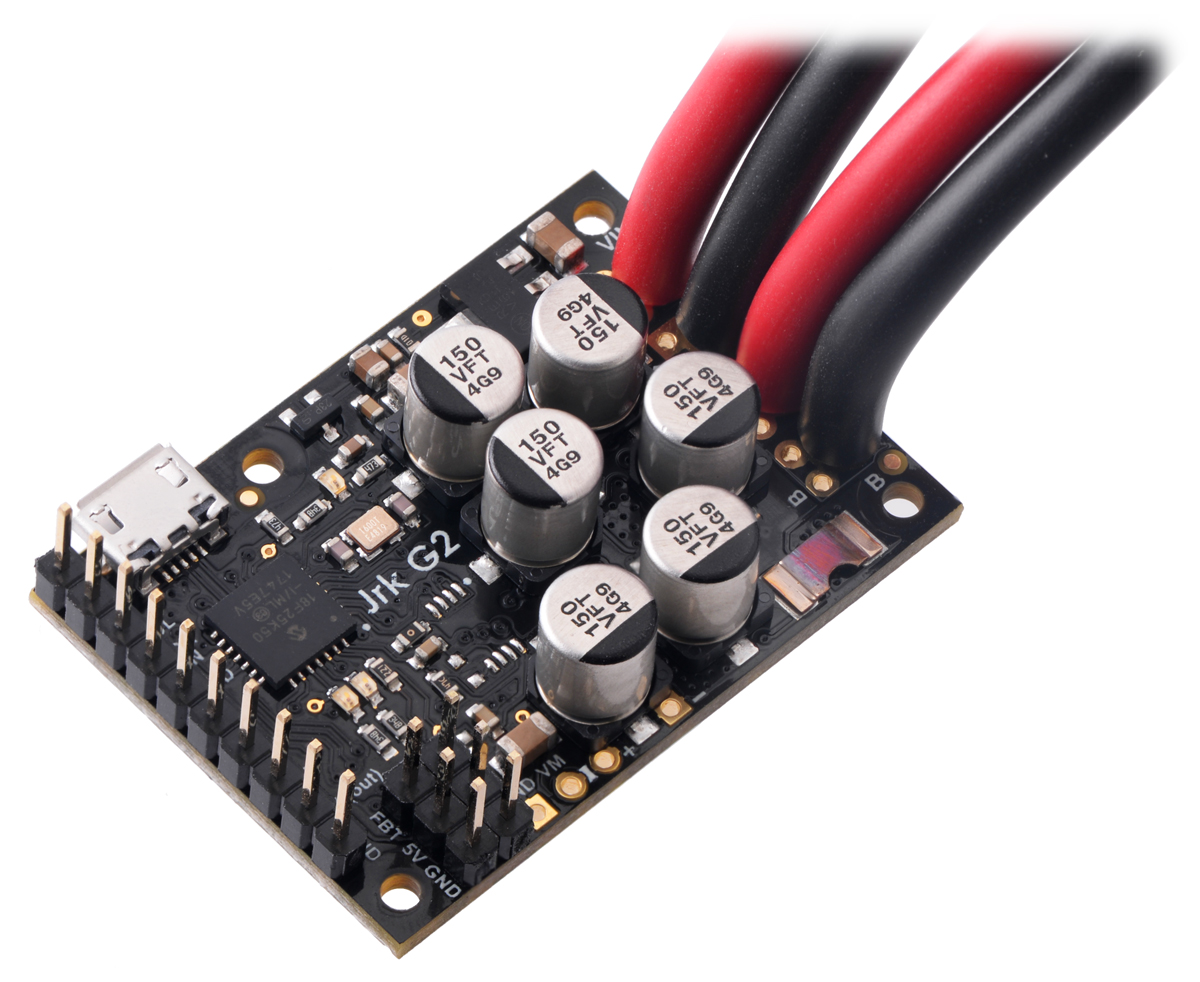
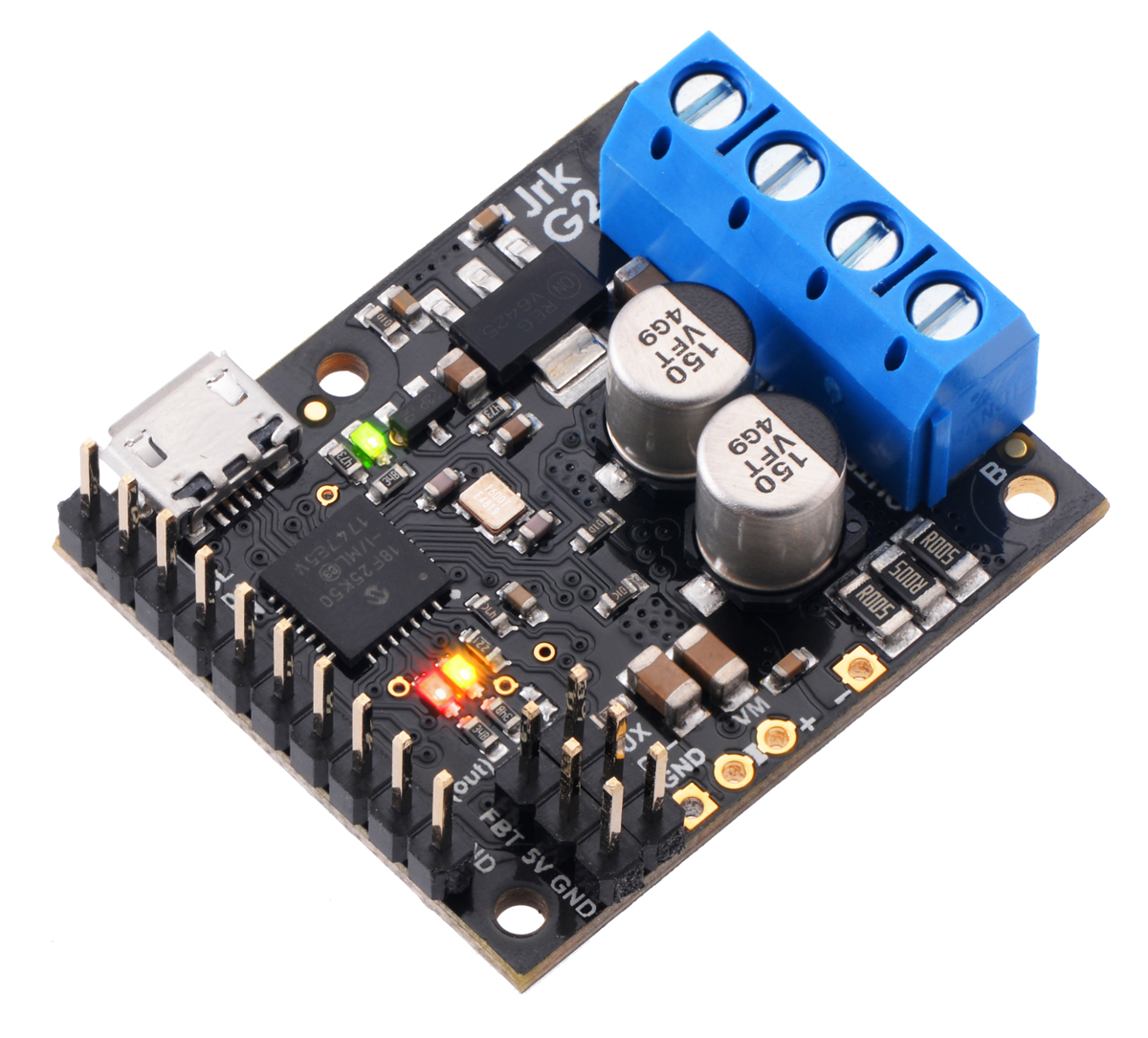

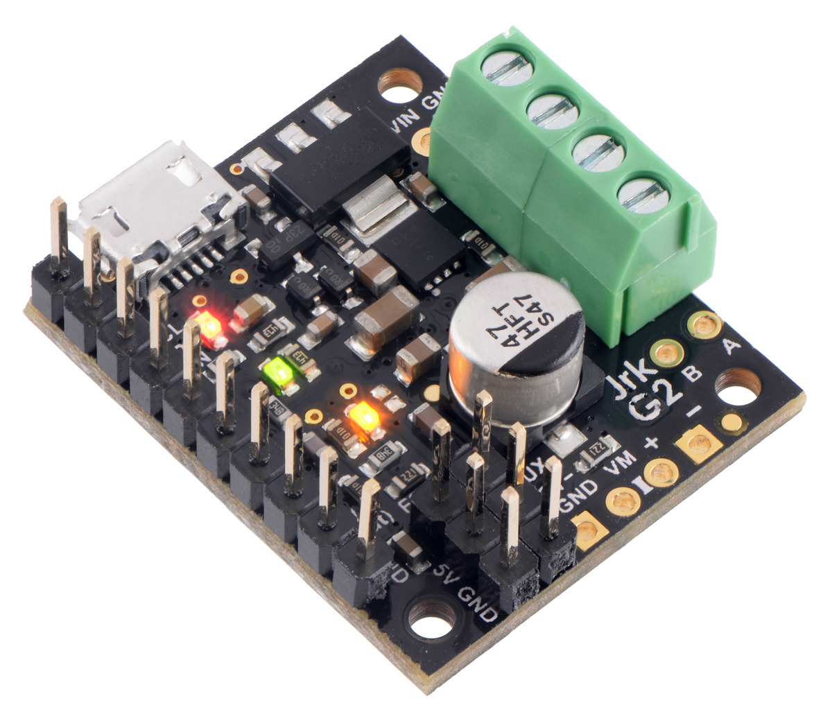
You should connect the motor leads to the OUTA and OUTB pins (which are labeled “A” and “B” on some boards). You should connect the negative terminal of the power supply to GND and the positive terminal of the power supply to VIN.
Next, turn on the power supply (if needed). Make sure that the Jrk’s yellow or red LEDs turn on at this point. If neither LED turns on, you might have connected power backwards, and you should fix it before connecting the Jrk to any other electronics.
Related products


Home | Forum | Blog | Support | Ordering Information | Lists | Distributors | BIG Order Form | About | Contact
© 2001–2026 Pololu Corporation
