Support » Pololu P-Star User’s Guide » 4. P-Star 45K50 Mini SV »
4.1. P-Star 45K50 Mini SV pinout and components
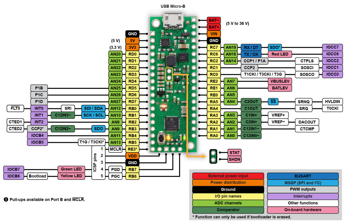 |
P-Star 45K50 Mini SV pinout diagram. |
|---|
This diagram identifies the I/O and power pins on the P-Star 45K50 Mini. The diagram is also available as a printable PDF (547k pdf). For more information about the PIC18F45K50 microcontroller and its peripherals, see Microchip’s PIC18F45K50 documentation.
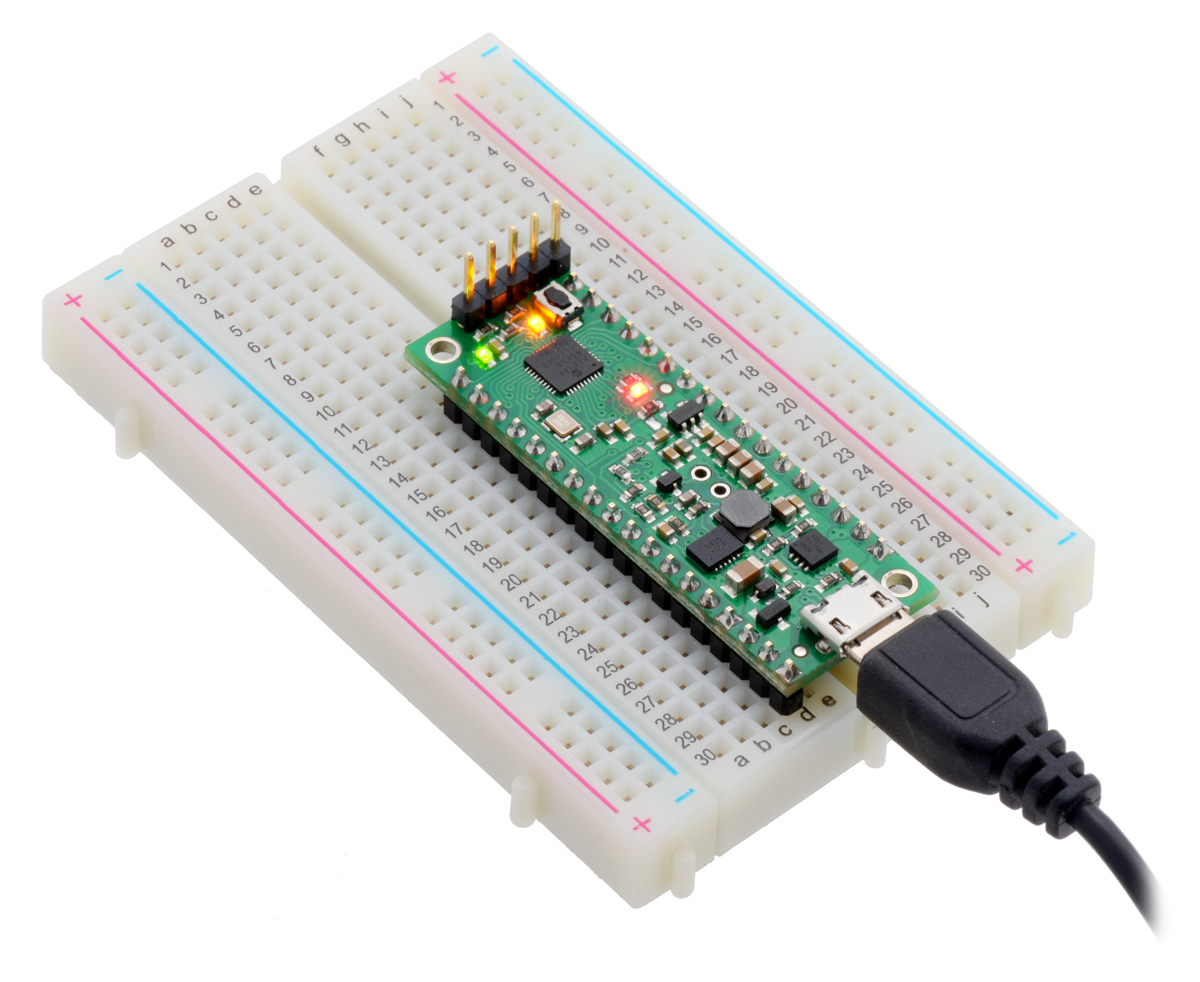
LEDs
The P-Star 45K50 Mini has three indicator LEDs. These LEDs are connected in the same way on all P-Stars.
The yellow LED is connected to RB6. Driving this pin high turns on the LED. In bootloader mode, the bootloader drives this line high to turn on the LED (see Section 6.4) but never drives it low. If this line is high when the microcontroller starts up, the microcontroller will go into bootloader mode. A button can be connected to RB6 as described in Section 5.2. RB6 has an on-board pull-down resistor to ensure that its voltage goes all the way down to 0 V when not being driven.
The green LED is connected to RB7, and lights when the pin is driven high. In bootloader mode, the bootloader drives this line high to turn on the LED (see Section 6.4) but never drives it low.
The red LED is connected to RC6, and lights when the pin is driven low. RC6 is the microcontroller’s serial TX line, so the red LED serves as an indicator for when the board is transmitting serial data. If you are not using serial, the LED can be used as a normal LED. To avoid interference with connected serial devices, the bootloader does not use this LED.
Connectors
The P-Star includes a USB Micro-B connector that can be used to connect to a computer’s USB port via a USB A to Micro-B cable (not included). The USB connection can be used to transmit and receive data from the computer, and a preloaded USB bootloader makes it possible to program the board over USB. The USB connection can also provide power to the P-Star.
The board also has five pins arranged so that they can be directly plugged into a standard In-Circuit Serial Programming (ICSP) connector, such as the one found on the PICkit 3. More information about programming with the PICkit 3 can be found in Section 7. The five pins are: MCLR, VDD, GND, RB7/PGD, and RB6/PGC. The MCLR pin is pin 1.
Power
The P-Star 45K50 Mini SV can either be powered directly from the USB 5 V supply or from an external voltage source between 5 V and 36 V, which is regulated to 5 V by a 500 mA ISL85415 switching step-down (buck) converter from Intersil. (We also make a standalone regulator based on this integrated circuit.). The board also has an auxiliary linear regulator producing 3.3 V.
The board’s power selection circuit uses the TPS2113A power multiplexer from Texas Instruments to choose whether its 5 V supply is sourced from USB or an external supply via the regulator, allowing both sources to be connected at the same time and enabling the P-Star to safely and seamlessly transition between them. The TPS2113A is configured to select external power unless the regulator output falls below about 4.5 V. If this happens, it will select the higher of the two sources, which will typically be the USB 5 V bus voltage if the P-Star is connected to USB. The currently selected source is indicated by the STAT pin in the middle of the board; this pin is an open-drain output that is low if the external power source is selected and high-impedance if the USB supply is selected. The current limit of the TPS2113A is set to about 1.9 A. For more information about the power multiplexer, see the TPS2113A datasheet (1k redirect).
In some situations, it might be undesirable for the P-Star 45K50 Mini to draw power from an external source when it is connected to USB. If this is the case, the regulator can be disabled by driving the regulator shutdown pin, SHDN, high; this shuts down the regulator and causes the power mux to fall back to USB power. For example, this could allow a battery-powered device to turn off the regulator and avoid draining its battery while it is connected to a computer.
USB power input: The P-Star can be powered from the USB 5 V bus voltage (VBUS) if it is connected to a USB cable. It will draw power from USB only if its external voltage source is disconnected.
Reverse-protected power inputs: The BAT+ and BAT− are power inputs with reverse-voltage protection. These are the recommended pins to use when connecting an external power supply because they allow the P-Star’s reverse-voltage protection circuit to help prevent it from being damaged by accidentally reversed power connections.
VIN power output (or alternative input): When power is supplied through the BAT pins, the VIN pin can be used as an output to supply reverse-protected power to other devices. Alternatively, the external supply can be connected directly between VIN and GND, bypassing the reverse-voltage protection.
5V power output: This pin provides access to the board’s 5 V supply, which comes from either the USB 5 V bus voltage or the on-board switching regulator, depending on which power sources are connected and enabled.
3V3 power output: This pin gives access to the output of the on-board 3.3 V linear regulator, which can provide a few hundred milliamps of current.
VDD: The VDD pin powers the microcontroller and is connected directly to the 5V power output.
|
|
USB power sensing
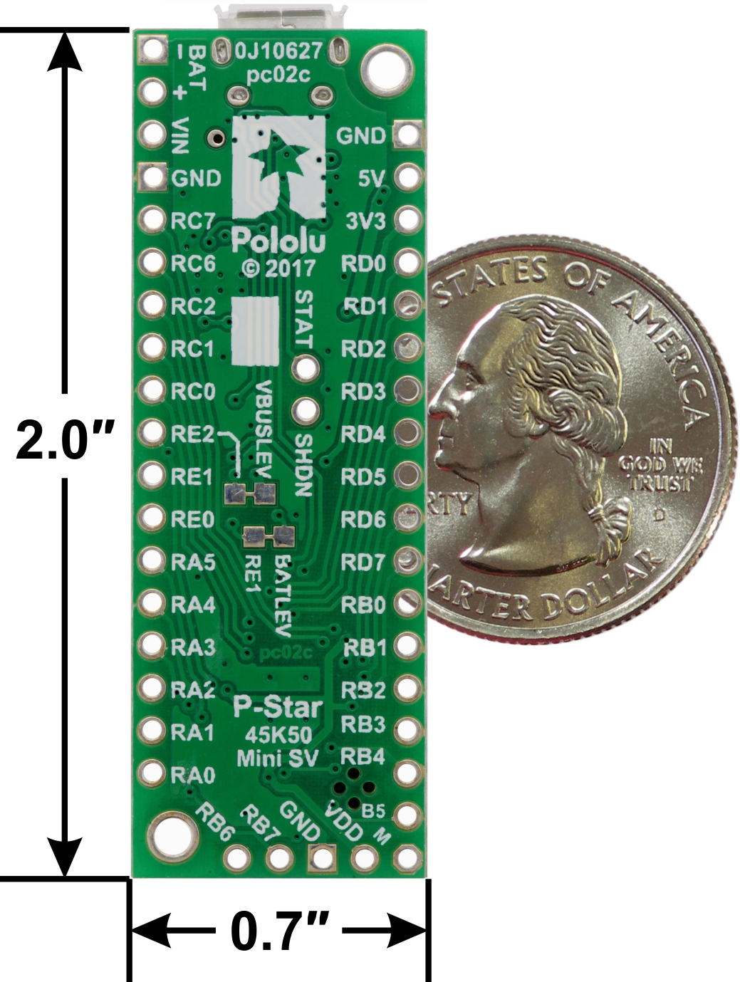
The voltage from USB (VBUS) powers a voltage divider that produces a voltage called VBUSLEV that is 91% of VBUS. By default, VBUSLEV is connected to the RE2 pin through a cuttable trace on the bottom of the board. This means that RE2 can be used as a digital or analog input to detect the presence of USB power. Cutting the trace between the RE2 and VBUSLEV pads on the bottom of the board allows RE2 to be used for other purposes. You can use solder to reconnect the two nodes.
External power sensing
The voltage on VIN powers a voltage divider that produces a voltage called BATLEV that is 9% of VIN. By default, BATLEV is connected to the RE1 pin through a cuttable trace on the bottom of the board. This means that RE1 can be used as an analog input to measure the external power supply voltage. Cutting the trace between the RE1 and BATLEV pads on the bottom of the board allows RE1 to be used for other purposes. You can use solder to reconnect the two nodes.
Reset button
The pushbutton on the P-Star 45K50 Mini resets the microcontroller when it is pressed.
Crystal
The P-Star 45K50 Mini has a precision 16 MHz crystal. By default, this crystal is used to provide a clock signal for the microcontroller and its peripherals.
Included hardware
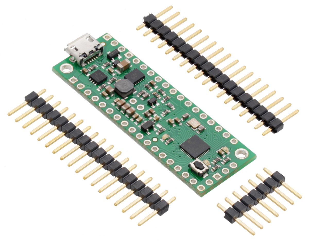
Two 1×18-pin breakaway 0.1″ male headers and one 1×7-pin breakaway 0.1″ male header are included with the P-Star 45K50 Mini. These header pins can be soldered in to use the board with perfboards, breadboards, or 0.1″ female connectors.
|
|
Related products


Home | Forum | Blog | Support | Ordering Information | Lists | Distributors | BIG Order Form | About | Contact
© 2001–2026 Pololu Corporation
