Support » Pololu Orangutan USB Programmer User’s Guide »
3. Module Pinout and Components
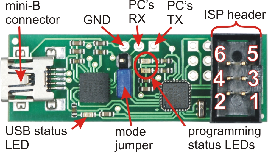 |
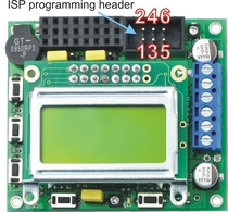
Pololu Orangutan USB Programmer labeled top view |
|---|
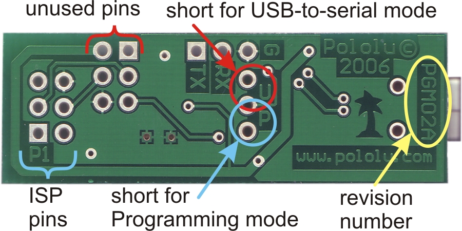 |
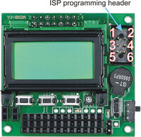
Pololu Orangutan USB Programmer labeled bottom view |
|---|
USB-to-Serial Adapter Mode:
The location of the blue mode jumper determines whether the device will function as a programmer or a USB-to-serial adapter. When the mode jumper spans the two pins that are marked on the bottom of the board with a “U”, the computer’s RX line is connected to the pad labeled RX and the device will function as a basic USB-to-serial adapter. The RX and TX pads are labeled from the computer’s perspective, so to make use of the USB-to-serial adapter you need to connect the programmer’s RX pad to your target’s TX pin (PD1 on the Orangutan/3pi) and the TX pad to your target’s RX pin (PD0 on the Orangutan/3pi) while in USB-to-serial mode. These pads expect logic-level signals (i.e. 0 V lows, 5 V highs).
Programmer Mode:
When the blue mode jumper spans the two pins that are marked on the bottom of the board with a “P”, the computer’s RX line is connected to the programming microcontroller and the device will function as an in-circuit AVR ISP programmer. The computer’s TX line is always connected to both the pad labeled TX and the programming microcontroller.
Revision Number:
There are currently two versions of the Orangutan USB Programmer: PGM02A and PGM02B. The programmer’s revision number is written along the right side of the bottom of the PC board. The newer PGM02B revision has two key improvements over the original PGM02A: 1) it has the ability to accept firmware updates from Pololu (see Section 8) and 2) it won’t let you program your target device if that device is not powered, which can help prevent you from accidentally damaging your Orangutan/3pi. Please take note of your programmer’s revision number so you know which statements in this user’s guide apply to your specific programmer.
LEDs:
The green USB status LED near the mini-B connector will light when the Orangutan USB programmer is connected to a personal computer and functioning properly as a serial port. If you have not installed the programmer’s drivers before connecting it, this status LED will be off.
The red and green programming status LEDs near the center of the board will give you feedback when the Orangutan USB programmer is being used in programming mode. The green LED will flash every time the programmer receives a valid AVR ISP command packet from the personal computer to which it is connected. The red LED will flash every time the programmer sends information over the 6-pin ISP cable to the device being programmed. These LEDs do not do anything when the Orangutan USB programmer is in USB-to-serial mode.
If you have programmer version PGM02B, you will have additional LED feedback. Every time your programmer powers up (i.e. when you connect it to your computer), the red and green status LEDs will both light for five seconds. During this period, the programmer is receptive to firmware updates; you should avoid trying to program until the initial five seconds have elapsed and the two status LEDs have turned off. Additionally, if your programmer is not connected to a target device or if your target device is not powered, the programmer’s red LED will flash once per second to indicate that it will not let you program.
Connecting to Your 3pi Robot:
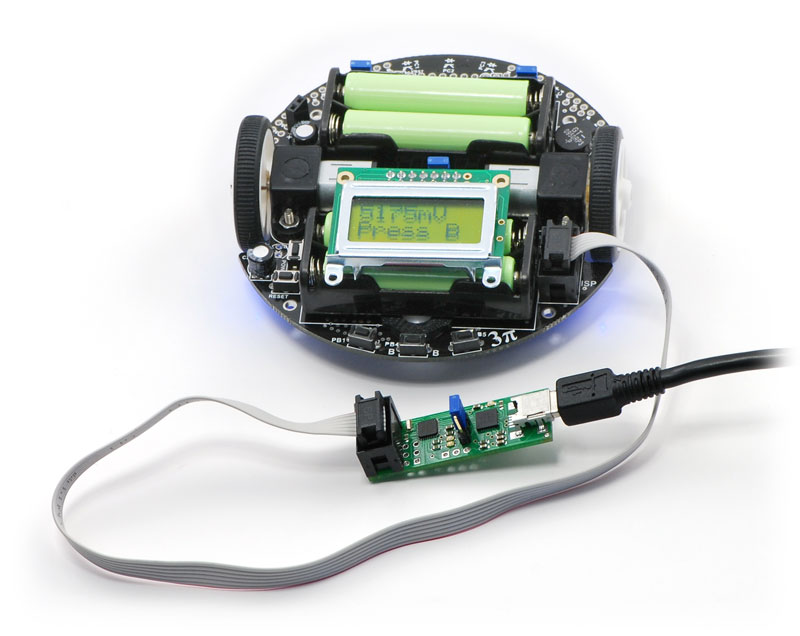 |
The Orangutan USB programmer connects to your 3pi robot via the included 6-pin ISP cable, which plugs into the 3pi’s keyed ISP port located just behind the right wheel as shown above.
Connecting to Your Orangutan:
|
|
|
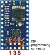
The Orangutan USB programmer connects to your Orangutan or Baby Orangutan via the included 6-pin ISP cable. The cable must be oriented so that the programmer’s ISP header pin 1 connects to your (Baby) Orangutan’s ISP header pin 1. Unlike the Orangutan, the Baby Orangutan does not come with a shrouded header to enforce correct cable orientation; the red wire and arrow mark on the cable’s ISP connector should be lined up with the arrow to pin 1 on the Baby Orangutan PCB. You will only be able to achieve this alignment by connecting to the top side of the Baby Orangutan PCB, so be very careful not to solder your 6-pin ISP header onto the wrong side of your Baby Orangutan!
Note: The programmer does not deliver power to the device it is programming, so your Orangutan must be turned on to be programmed. If you are using programmer version PGM02A, attempting to program an unpowered device will have unpredictable results; this might randomly change the fuse settings, which can in turn permanently disable your Orangutan (see Fuses in Section 5.b). If your programmer version is PGM02B, the programmer will not let you program an unpowered device (you will see the red status LED blink once per second if your target device is not powered). You must still take great care to ensure that your target device does not lose power during programming.
Related products


Home | Forum | Blog | Support | Ordering Information | Lists | Distributors | BIG Order Form | About | Contact
© 2001–2026 Pololu Corporation
