Support » Pololu Simple Motor Controller User’s Guide » 3. Getting Started »
3.3. Understanding the Control Center Status Tab
After installing the software and drivers for the Simple Motor Controller, it is a good idea to run the Pololu Simple Motor Control Center and look at the Status tab. The Status tab lets you monitor the status of your motor controller in real time and control the speed of the motor. The Status tab also shows what errors and limits are affecting your motor controller so it can help you quickly troubleshoot any issues you are having.
To use the Status tab, you should connect your Simple Motor Controller to your PC using a USB cable (not included) and run the Pololu Simple Motor Control Center. This is what the Status tab should look like initially, before you have modified any settings or connected anything to the Simple Motor Controller (besides USB):
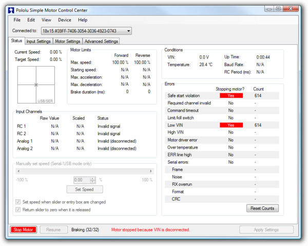 |
The Status tab in the Simple Motor Control Center should look like this when you first connect the controller to the PC. |
|---|
Target Speed and Current Speed
The Target Speed is the speed that the motor controller is trying to achieve. The Target Speed source is determined by the settings in the Input Settings tab, and can come from serial/USB commands, analog voltages, or RC signals.
The Current Speed is the speed at which the controller is currently your driving your motor. There are several reasons why the Current Speed might be different from the Target Speed: errors, acceleration limits, deceleration limits, brake duration, maximum speed limits, starting speed limits, and gradual temperature-based speed limiting. If any of these things are affecting the Current Speed, the appropriate part of the Status tab will be highlighted to let you know. Anything that is stopping the motor completely will be highlighted in red. Anything that is limiting the speed of the motor will be highlighted in yellow.
The Simple Motor Controller represents speeds internally as a number from -3200 (full reverse) to 3200 (full forward). However, by default the speeds in the Status Tab are displayed as percentages so -3200 (full reverse) is shown as -100.00% and 3200 (full forward) is shown as 100.00%.
Below the Target Speed label is a two-dimensional diagram that represents the values of the inputs that are used to set the Target Speed. This diagram is especially useful in RC or Analog mode with Mixing enabled because it graphically shows you the value of both input channels and makes it easier to tell how well the Simple Motor Controller is calibrated for your controller is.
Motor Limits
The Motor Limits box in the Status tab shows the current limits on the movement of the motor. These limits will be equal to the hard motor limits specified in the Motor Settings tab, unless you have temporarily changed the motor limits using the command-line utility (SmcCmd) or a serial command. For more information on these limits, see the section that documents the Motor Settings tab.
Input Channels
The Input Channels box in the Status tab shows the current status of the RC or Analog input channels of the device.
The Raw Value is the raw, unscaled value of the input channel. For RC channels, the Raw Value is the width of pulses received on the input line (RC1 or RC2). It is typically between 1000 μs and 2000 μs, and it is stored internally as an integer in units of quarter-microseconds (6000 corresponds to 1500 μs). For Analog channels, the Raw Value is the average voltage measured on the input line (A1 or A2). It is always between 0 mV and 3300 mV, and it is stored internally as a 12-bit integer (0 corresponds to 0 mV while 4095 corresponds to 3300 mV).
The Scaled Value is a number between -3200 and 3200 that is determined entirely by the Raw Value and the scaling parameters in the Input Settings tab. If the scaling parameters are set up correctly, then the Scaled Value should be 0 when the input is in its neutral position (if it has a neutral position), and they should be ±100 % (±3200 internally) when the input is moved to either extreme.
The Status column summarizes the state of each channel. Here are the different things you might see in the Status column:
- Valid: There is an RC or Analog input connected to this channel and it is working.
- Invalid (disconnected): This message is shown for Analog channels when the controller detects that they are disconnected. If you do not intend to use this channel, you do not need to worry about this message. Otherwise, to correct this situation, make sure that all three pins of your potentiometer or analog joystick are connected correctly to the three analog interface pins (see Section 4.4). The controller toggles the power supply on the Analog + pins in order to detect when your potentiometer is disconnected. This feature can be turned off in the Advanced tab, in which case you will not see the “Invalid (disconnected)” message.
- Invalid signal: This message is shown for RC channels when the controller detects no signal or a bad signal on the RC input. If you do not intend to use this channel, you do not need to worry about this message. Otherwise, to correct this situation, make sure that your RC receiver is powered and connected correctly (see Section 4.3), and check your RC pulse detection settings in the Advanced tab.
- Invalid (too high) and Invalid (too low): These messages are shown for Analog channels when the voltage read on the A1 or A2 pin is outside of the normal range, as specified by the Error min and Error max parameters for that channel in the Input Settings tab. To correct this error, you can re-configure the range of your analog input by clicking the “Learn…” button for that channel, or you can manually adjust the scaling parameters.
- Invalid (high signal) and Invalid (low signal): These messages are shown for RC channels when the pulse width measured on the RC1 or RC2 pin is outside of the normal range as specified by the Error min and Error max parameters for that channel in the Input Settings tab. To correct this error, you can re-configure the range of your RC input by clicking the “Learn…” button for that channel, or you can manually adjust the scaling parameters.
Conditions
The Conditions box in the Status tab shows miscellaneous information about the current state of the controller:
- VIN: This is the voltage of your power supply, measured on the VIN line. When your power supply is disconnected, this should read 0.0 V. This reading is continually compared to the VIN thresholds in the Advanced Settings tab and will generate an error and shut down the motor if it passes these thresholds. This allows a properly configured controller to avoid over-discharging your batteries.
- Temperature: This is a measurement of the temperature of the device. This reading is used prevent damage to the device by shutting down the motor when the board gets too hot (the over-temperature threshold is can be adjusted in the Advanced Settings tab). Please note that this product can get hot enough to burn you during normal operation. Take care when handling this product or other components connected to it. Parts of the board be significantly hotter than this reading, so you should not rely on this temperature reading when deciding whether it is safe to touch the board.
- Up Time: This is the total amount of time that the controller has been running since its last reset or power-up. The Up Time reading can be used to help identify if the controller has reset unexpectedly. You can determine the cause of a reset by looking at the pattern of the yellow LED (see Section 3.5), or you can look in the Device Information window, available from the Device menu. The Up Time reading will overflow back to zero after 49.7 days.
- Baud Rate: This is the current baud rate that the device is using on the TTL serial interface (RX and TX lines) in units of bits per second (bps). By default, the device is in Auto-detect baud rate mode, so this value will be “N/A” until the baud rate is detected. After a 0xAA byte is received on the RX line, the device will detect the baud rate and you can see it here. Please note that the Baud Rate display in the Status tab has nothing to do with the USB virtual COM port (it doesn’t matter what baud rate you use when connecting to the virtual COM port).
- RC Period: This is the period of the RC signal on the RC1 input channel. You can use this reading to help you make the RC period settings in the Advanced Settings tab more strict so that the controller can better identify bad RC signals. If the signal on RC1 is invalid, this reading is reported as “N/A”.
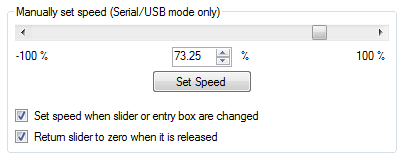 |
Manually set speed (Serial/USB mode only)
The Manually Set Speed box in Status tab allows you to control the speed of your motor over USB by using a scrollbar or by typing in a speed. To use this feature, the Input Mode (configured in the Input Settings tab) must be USB/Serial, and there must be no errors currently stopping the motor. You will need to press the Resume button if you have not disabled Safe Start or if you previously pressed the Stop Motor button.
Related products


Home | Forum | Blog | Support | Ordering Information | Lists | Distributors | BIG Order Form | About | Contact
© 2001–2026 Pololu Corporation
