Support » Pololu Orangutan SVP User’s Guide »
4. Module Pinout and Components
The Orangutan SVP contains a programmable AVR ATmega324PA or ATmega1284P microcontroller connected to two motor drivers for direct control of two DC motors, a 16×2 character LCD, a buzzer, three user pushbuttons, two user LEDs, and a demultiplexer for servo control. The AVR is also connected to an auxiliary processor (a PIC18F14K50) that provides access to the battery voltage, a 10 kilo-ohm user trimmer potentiometer, and four additional input lines. The auxiliary processor also serves as a programmer for the main processor, meaning that an external programmer is not required, but you can use one if you want to. The auxiliary processor also allows for USB communication between the AVR and a personal computer, and acts as a USB-to-serial converter.
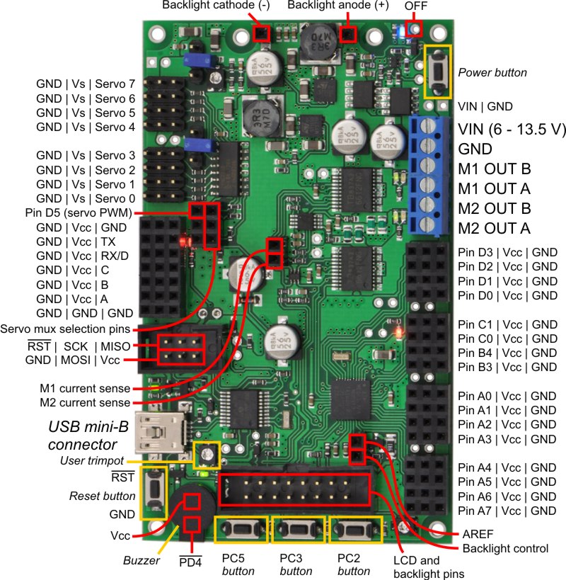 |
Orangutan SVP fully assembled PCB with pins labeled. |
|---|
These and the rest of the main features of the module are labeled in the picture above and in more detail in the Orangutan SVP reference diagram (82k pdf). Most of the connection points are also indicated on the silkscreen on the back side of the PCB, as shown below. The overall unit dimensions are 3.7" × 2.2", and four 0.086" mounting holes, suitable for #2 screws, are located 0.1" from the corners of the board.
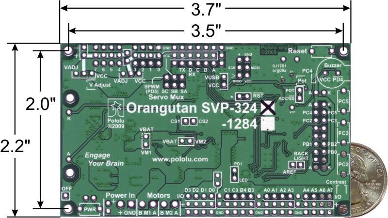 |
Orangutan SVP-324 with dimensions. |
|---|
Power & Motor Connections
Power for the Orangutan SVP should be connected to the positive (+) and ground (GND) terminals near the words “Power In” on the board. The input voltage (VIN) of the power supply should be 6 – 13.5 V, from which the on-board regulator generates the 5 V supply (VCC) that is used to power the logic.
The Orangutan SVP has one TB6612FNG motor driver for each motor output. Each motor driver can deliver a continuous 2 A, and can briefly deliver up to 6 A. If you are not taking extra steps to keep the motor driver cool, such as using a heat sink, exceeding this continuous current rating for too long will cause the motor driver to heat up and trigger its built-in thermal shutdown.
By default, the motor drivers are powered from VBAT, which refers to the input voltage (VIN) after passing through reverse protection and the power switch circuit. However, you can disconnect VBAT from the motor drivers by cutting the labeled traces on the bottom of the board (VBAT-VM1 and VBAT-VM2). This allows you to connect some other power supply to the motor drivers, such as VADJ (see below). The motor drivers have an operating range of 4.5 – 13.5 V, so your power supply should be in that range, and should be capable of supplying all the current that your motors might draw.
USB Power
When connected to a computer, the USB connection provides a 5 V power supply. If an external power supply is present, the unit will run off of the external supply and not draw any power from USB. If only the USB power is present, then by default the auxiliary processor will be powered from USB, but the AVR and the VCC power pins on the board will not be powered. An option is available for powering the entire board from USB. See Section 11 for more information.
Motors
The motor drivers are controlled by two of the AVR’s hardware PWM outputs from eight-bit Timer2 for speed control, along with two digital outputs for direction control. This lets you achieve variable motor speeds using hardware PWMs rather than processor-intensive software PWMs on the motor control lines. You can control the motors using the functions in the OrangutanMotors section of the Pololu AVR C/C++ Library.
For each motor, the Orangutan SVP has a current-sensing circuit that produces an output voltage proportional to the current the motors are using (850 mV/A). The respective outputs of these circuits are labeled CS1 and CS2, and they are accessible near the center of the board.
User I/O & Power Outputs
Sixteen user I/O lines can be accessed via the four 4×3 0.100" female headers along the lower edger of the board, as shown below. Each I/O line has associated power and ground connections for easy connections to sensors: the exterior (bottom) pin is ground, the middle pin is power, and the interior (top) pin is signal and connects directly to an AVR I/O line.
For each four-pin bank of I/O lines, you can configure which power voltage is supplied to the power (middle) pins. By default, the power pins are connected to VCC (5 V). You can cut a trace on the bottom of the board to disconnect them from VCC. This will leave the power pins connected to one through-hole, which can be connected to a different power source, such as VADJ, which is available elsewhere on the board.
The total current available on the VCC (5 V) line is 3 A, meaning you can power servos and other high-power peripherals directly from your regulated voltage.
LCD
The Orangutan SVP is supplied with a removable 16×2 character LCD with backlight that uses the common HD44780 parallel interface (109k pdf). A different LCD can be connected with an appropriate cable. The AVR has four I/O lines connected to LCD data lines DB4 – DB7 (i.e. is configured to use the LCD in 4-bit mode) and three I/O lines connected to the three LCD control lines RS, R/W, and E. Please note that the LCD data lines are also shared by the user pushbuttons and the green user LED. You can print to the LCD using the functions in the OrangutanLCD section of the Pololu AVR C/C++ Library.
The LCD’s backlight can be turned off by driving the BACKLIGHT line low. Adjustable dimming of the LCD can be achieved by connecting the line to a free PWM output.
The AVR’s AREF pin is available next to the backlight pin.
Pushbuttons
The Orangutan SVP has five total pushbuttons: a power on/off button located on the right side of the bottom edge of the board, a reset button located on the left side of the top edge of the board, and three user pushbuttons located along the left edge of the board. Please note that the power button disconnects the external power supply from the entire board, while the reset button connects directly to the AVR’s RESET pin and does not disconnect the power supply.
The user pushbuttons, from top to bottom, are on pins PC5, PC3, and PC2. Pressing one of these buttons pulls the associated I/O pin to ground through a resistor. You can detect button pushes using the functions in the OrangutanPushbuttons section of the Pololu AVR C/C++ Library. The library takes care of configuring the pins as inputs, enabling the AVR’s internal pull-up resistors, and debouncing (accounting for the fact that pushbuttons physically bounce when pressed).
Buzzer
The Orangutan SVP comes with a buzzer controlled by pin PD4. If you alternate between driving the buzzer pin high and low at a given frequency, the buzzer will produce sound at that frequency. You can use the functions in the OrangutanBuzzer section of the Pololu AVR C/C++ Library to play notes in the background (using hardware PWM) while the rest of your processor performs other tasks.
Trimpot
The Orangutan SVP comes with a 10 kilo-ohm user trimmer potentiometer, located between the USB connector and the LCD connector. The trimpot is connected to the auxiliary processor, which measures its output voltage and reports it to the AVR.
You can disconnect the trimpot from the auxiliary processor by cutting the labeled trace between POT and ADC/SS on the bottom side of the board. This gives you two options for that line: you can use it as a general-purpose analog input by connecting some other output to it, or you can connect it to one of your AVR’s free I/O lines and use it as the SPI slave-select line for the auxiliary processor, allowing you to communicate with some other SPI peripheral.
Programming Connector
The Orangutan SVP has a 6-pin programming connector on the upper left side. This gives you the option of using an AVR ISP in-system programmer from Atmel or a compatible programmer, such as our Pololu USB AVR Programmer to program the AVR. This is not necessary, though, because the Orangutan SVP’s auxiliary processor can serve as an AVR ISP programmer for the AVR.
By default, pin 5 of the Programming connector, which is labeled by an asterisk (*), is connected to the AVR’s RESET line, which is necessary for ISP programming by an external device). However, you can disconnect those two pins by cutting a labeled trace on the bottom of the circuit board. This gives you the option of using that line for some other signal.
Auxiliary I/O & Power Outputs
The Orangutan SVP has five auxiliary I/O lines that are connected to the auxiliary processor. Each I/O line has associated power and ground connections for easy connections to sensors: the exterior (top) pin is ground, the middle pin is power (VCC), and the interior (bottom) pin is signal and connects directly to an auxiliary processor I/O line. The TX line is the serial transmit line. It transmits TTL-level serial bytes received from the computer on the “Pololu Orangutan SVP TTL Serial Port”. The lines A, B, C, and D/RX can be configured to do different things. They can function as three analog inputs plus a serial receive line, as four analog inputs, or as the inputs for two quadrature encoders. See the OrangutanSVP section of the Pololu AVR C/C++ Library for more information.
Servo Demultiplexer
The hardware in the upper-right corner of the Orangutan SVP allows you to control up to 8 servos without sacrificing a large number of I/O lines or processor cycles. You can control servos using the functions in the OrangutanServos section of the Pololu USB AVR C/C++ library.
The input signal of the demultiplexer is connected to pin PD5 on the AVR. If you are not using PD5 to control servos, you can use it as a general-purpose digital I/O line or PWM output.
The three output-selection pins of the multiplexer (SA, SB, and SC) are available in the header near the multiplexer so they can be wired to free I/O lines on the AVR, allowing you to switch between servos. The output-selection pins have pull-down resistors, so if you have four servos or fewer you can leave some of them disconnected.
The eight output pins of the multiplexer are available in two 4×3 headers. These lines have current-limiting resistors on them. Each multiplexer output line has associated power and ground connections for easy connections to the servos: the exterior (top) pin is ground, the middle pin is power. For each bank of servos, you can configure which power supply is connected to the power pins, using the provided headers and jumpers. You can power the servos from VCC, VADJ (see below), or a separate power supply. The fully assembled version ships with a jumper attached to just the middle pin of each of the two servo power selection banks. In this default orientation, the jumper supplies no power to the servo power rail.
 |
Orangutan SVP with key integrated hardware labeled. |
|---|
Adjustable Voltage (VADJ)
In addition to the 5 V regulator that supplies VCC, the Orangutan SVP comes with an adjustable voltage regulator. Both regulators can supply a current of 3 A. The adjustable voltage regulator draws current from the external power supply, and produces an output voltage called VADJ. The trimmer potentiometer in the upper right corner of the board determines VADJ. If you turn the trimpot all the way counter-clockwise, VADJ goes down to about 2.5 V. If you turn it all the way clockwise, VADJ rises to 85% of VIN. The adjustable voltage regulator will be off when the main power is switched off.
In general, it is advantageous to power servos and other high-power devices from VADJ (instead of VCC), because if the peripherals draw too much current for the power supply to handle the AVR will not be affected.
LEDs
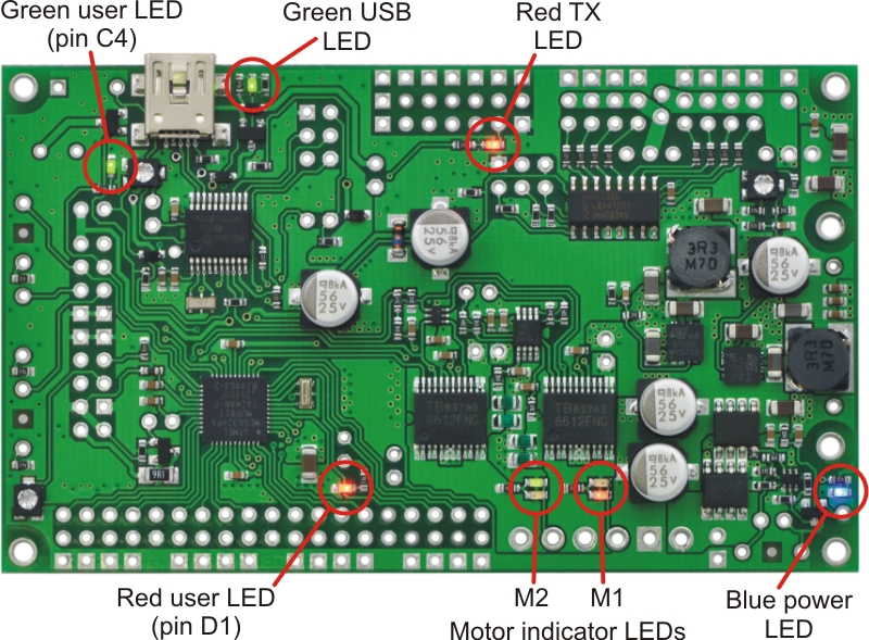 |
Orangutan SVP LEDs. |
|---|
The Orangutan SVP comes with 9 LEDs:
- A blue power LED is located next to the power button.
- There are four motor indicator LEDs located near the motor outputs. A green LED lit indicates that the corresponding motor is being driven “forward” (the voltage on output B is higher than the voltage on A). A red LED indicates that the corresponding motor is being driven in “reverse” (the voltage on output B is lower than the voltage on output A).
- A red user LED is located near the AVR I/O banks. The LED is connected to the user I/O line PD1. It will light if you set PD1 as a low output. Since PD1 is the serial transmit line for UART0 (TXD0), the LED will flicker whenever serial data is being transmitted from the AVR. The LED can be disconnected from PD1 by cutting a labeled trace (PD1-LED) on the bottom of the board.
- A green user LED is located between the trimpot and the buzzer. It will light if you set PC4 as a high output. Note that PC4 is also used as an LCD data line, so you will see the green LED flicker when you update the LCD.
- Another green LED is located near the USB connector. This LED is controlled by the auxiliary processor and indicates the status of the USB connection. When the USB is disconnected, or the device is in the USB Suspend state (because the computer went to sleep), the green LED is off. When you connect the device to a computer via USB, the green LED will start blinking slowly. The blinking continues until it receives a particular message from the computer indicating that the drivers are installed correctly. After the programmer gets this message, the green LED will be on, but it will flicker briefly when there is USB activity.
- Another red LED is located near the header for the auxiliary processor’s TX line. This LED is tied to the TX line, so it will flicker whenever the auxiliary processor is transmitting TTL-level serial bytes from the computer. This LED will also blink when the auxiliary processor powers up to indicate bad startup conditions. Two blinks indicates that a brown-out reset was triggered: the processor’s VDD dropped below 3.0 V. If this happens to you, check your power connections and battery voltage, and make sure you are not drawing too much power from the board.


Home | Forum | Blog | Support | Ordering Information | Lists | Distributors | BIG Order Form | About | Contact
© 2001–2026 Pololu Corporation
