Support » Sample Project: RC 3pi »
3. Construction
Connecting the Receiver to the 3pi
Begin by soldering the 2×7 female header where it fits between the 3pi’s gearmotors, as shown in the picture below. If you do not have the header, you can still build an RC 3pi; you will need to solder the wires directly to the 3pi’s circuit board in the places where they would have been inserted into the female header.
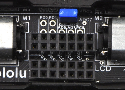 |
A 2×7 female header soldered into the 3pi expansion pin holes. |
|---|
Attach one end of each servo cable to a channel on the RC receiver. Then, with the 3pi turned off, connect the wires as shown in the picture below:
- Connect the signal pin (usually the wire with white or yellow insulation) of one servo cable to PC5 and the signal pin of the other servo cable to PD0. These connections are made with blue wires in the picture below.
- Connect the power pin (usually the wire with red or orange insulation) of one servo cable to VBAT on the 3pi. This will power the receiver directly off of the 3pi’s batteries.
- Connect the ground pin (usually the wire with black or brown insulation) of one servo cable to GND on the 3pi.
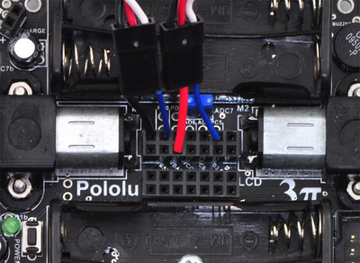 |
The wiring of a radio-controlled 3pi. |
|---|
Remove the PC5 jumper and use double-sided tape to secure the RC receiver and its antenna to the 3pi as shown in the picture below. Note that the receiver might fit better if you first remove the LCD.
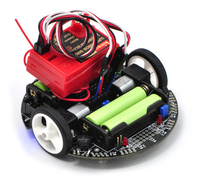 |
A radio-controlled 3pi. |
|---|
Design Considerations and Restrictions
In this project, we used pins PD0 and PC5 because they are available digital inputs. We avoided using PD1 because the LED on that line can pull the signal down and lead to poor performance, depending on how strongly the receiver drives its outputs. ADC6 and ADC7 can only be used as analog inputs and are not ideal for measuring the widths of digital pulses with good accuracy.
Another option is to remove the LCD and use some of those I/O lines to process the signals, though you must be careful not to call any LCD control functions if your receiver channels are connected to pins on the LCD port. If you use pins from the LCD port, you would most likely want to avoid PD7, which has an LED on the line.
Note: Do not use any of the Pololu AVR library’s line sensor functions while your receiver is connected to PC5. Even with the PC5 jumper disconnected, the library’s line sensor routines will attempt to control the emitters by driving PC5 high for the duration of the sensor read and then driving PC5 low. You want PC5 to remain an input for duration of the time it is connected to your receiver. If you want to use the 3pi’s line sensors while your 3pi is under radio control, you will need to modify the library slightly.
Related products


Home | Forum | Blog | Support | Ordering Information | Lists | Distributors | BIG Order Form | About | Contact
© 2001–2026 Pololu Corporation
