Support » Sample Project: 3pi Wall Follower »
3. Construction
Begin by soldering the 2×7 female header where it fits between the 3pi’s gearmotors. Also solder the 1×2 female header into the VCC and GND on the front-right side of the 3pi—this header will be used to power one of your Sharp distance sensors. If you do not have the headers, you can still build a 3pi wall follower; you will need to solder the wires coming from the distance sensors directly to the PCB in the places where the female headers are inserted.
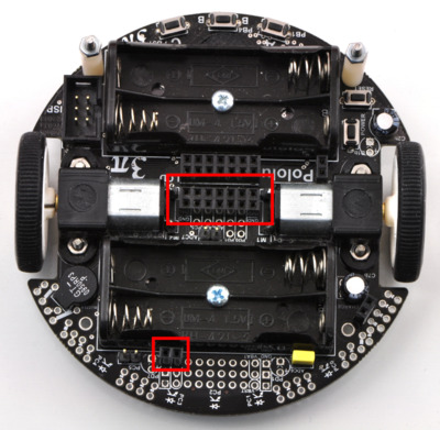 |
3pi with additional female headers soldered in place. |
|---|
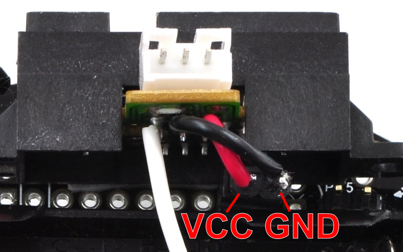
Prepare the two distance sensors by connecting a 3-pin female JST PH-style cables for Sharp distance sensors. If you do not have this cable, you can solder three wires to the three leads as shown in the picture, but the $0.99 cable makes things much easier. Break a 2×7 and a 1×2 male header off of the 2×40 male header. Solder the power and ground wires of one distance sensor to a 1×2 male header that will connect to the 1×2 female header. Solder the other distance sensor’s wires to the 2×7 block as shown in the picture below: the other distance sensor’s power and ground are connected to VCC and GND, and the signal wire of the distance sensors are connected to ADC7 and PC5. The front-left distance sensor’s signal wire should be connected to ADC7 (labeled AD7 on the 3pi silkscreen) and the front distance sensor’s signal wire should be connected to PC5.
|
|
|


Remove the ADC7 and PC5 jumpers and use double sided tape to secure the two distance sensors to the front of the 3pi as shown in the picture below. Mount the distance sensors with a slight upward angle so that they do not see the floor if the robot tips forward.
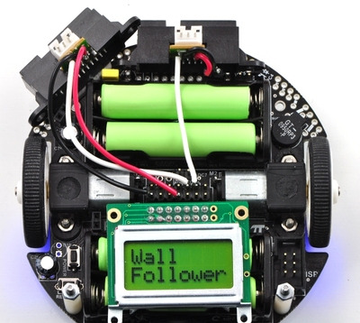 |
Fully constructed 3pi wall follower. |
|---|
Note: You must be careful if you also want to use the Pololu AVR library’s line sensor routines while your distance sensor is connected to PC5. If you want to use the 3pi line sensors, you should call pololu_3pi_init_disable_emitter_pin as described in Section 19 of the Pololu AVR Library Command Reference to disable the library’s control of PC5. Otherwise, even with the PC5 jumper disconnected, the Pololu AVR library’s line sensor routines will attempt to control the emitters by driving PC5 high for the duration of the sensor read and then driving PC5 low. Alternatively, you can connect your distance sensor to ADC6 instead of PC5.
Related products


Home | Forum | Blog | Support | Ordering Information | Lists | Distributors | BIG Order Form | About | Contact
© 2001–2026 Pololu Corporation
