Support » PIC-Based, Obstacle-Avoiding Robot »
3. Hardware Construction
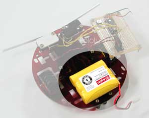 |
Begin by assembling the robot chassis. You should mount the battery pack on the rear of the robot, above the ball caster, to balance the weight of the motors. Double-sided foam tape is a convenient method of attaching the battery pack; it can also be secured with cable-ties by using the rectangular holes on both sides of the ball caster. If you are using a battery holder, you can easily drill mounting holes through the holder or the chassis if existing holes do not line up.
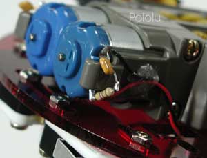 |
When soldering to the motor leads, be careful not to damage them. Soldering a small capacitor across the motor leads can improve the performance of the motor controller and lower interference with other electronics on your robot. We used a 0.1 uF ceramic capactitor.
The picture to the right shows a resistor in series with the capacitor. In general, such a resistor limits the current wasted by the PWM (pulse width modulation) in charging and discharging the capacitor. However, the relatively low, 600 Hz PWM frequency of the motor controller makes this resistor unnecessary; we saw no added benefit when we added the resistor.
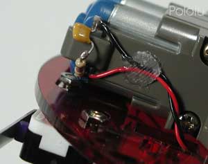 |
Because the motor leads are fragile, it is important to provide strain relief for the wires you connect to the motor. For our example, we hot-glued the leads to the side of the gearbox, as shown in the picture. Securing the wires this way will allow you to manipulate the other end of the wires without worrying about breaking off the motor leads. Note that the glued wires prevent removal of the motors from the gearbox. Hot glue has the advantage of not being entirely permanent; if necessary, it’s not too difficult to free the wires.
We have kept the motor capacitor exposed for the purposes of these pictures, but it’s a good idea to protect them as much as possible, especially since they are low to the ground and on the front end of the robot.
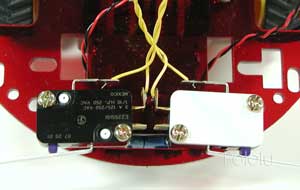 |
To keep this project as simple as possible, we limit our sensors to two snap-action swtiches for front collision detection. Of course, you can add more sophisticated sensors for more interesting behavior.
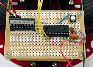 |
As you can see in the picture to the right, there isn’t much to the electronics. We soldered the circuit on a small perforated board, but you can also use a solderless breadboard. The small pushbutton switch on the top right and the resistor below it make up an optional reset circuit. The only other components are the PIC, the resonator (lower right), and the motor controller. No additional resistors are required for the bump switches because we use the PIC’s internal pull-up resistors on port B.
 |
The main reason for using the PIC16F628 is that it has a hardware UART; to make use of it, we must connect the TX pin, pin RB2, to the motor controller’s serial input. Connecting the motor controller reset pin is optional, but using it prevents any baud rate detection problems during power-up. If you don’t have any extra I/O lines, you can connect the reset input to the PIC reset circuit.
Note that the bumper switches must be connected to port B pins in order to make use of the PIC’s internal pull-up resistors. Nine of the PIC I/O lines are unused and available for expansion. As you add additional electronics, you may need to add 0.1 uF bypass capacitors from power to ground to keep the power supply clean.
As you can see in the picture to the right, there isn’t much to the electronics. We soldered the circuit on a small perforated board, but you can also use a solderless breadboard. The small pushbutton switch on the top right and the resistor below it make up an optional reset circuit. The only other components are the PIC, the resonator (lower right), and the motor controller. No additional resistors are required for the bump switches because we use the PIC’s internal pull-up resistors on port B.


Home | Forum | Blog | Support | Ordering Information | Lists | Distributors | BIG Order Form | About | Contact
© 2001–2026 Pololu Corporation
