Support » Understanding Destructive LC Voltage Spikes »
2. Test Setup
The circuit for this test consists of just three main components: a power supply, a switch, and a capacitor. We observe the voltage across the capacitor with an oscilloscope to see the start-up transients to which a circuit, represented by a load resistor, would be exposed if it were powered this way. A schematic diagram of the test circuit is shown below:
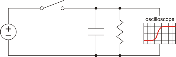 |
Schematic diagram for using an oscilloscope to measure the voltage across a capacitor after a switch is closed. |
|---|
The capacitor we used is a 10 uF (nominal; we measured it to be approximately 9 uF) multi-layer ceramic capacitor (MLCC) in a 1206 surface-mount package, which we soldered to a 2-pin male header to allow for easy breadboard use:
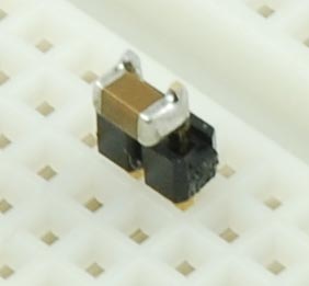 |
Ceramic capacitor soldered to 2-pin male header for breadboard use. |
|---|
The capacitor selection is important because other types of capacitors, such as electrolytic capacitors, have much higher equivalent series resistance (ESR), which dampens the spikes we are exploring. Low ESR is often a good thing, and the small size of ceramic capacitors makes them very common in small, mass-produced electronics products.
With a representative capacitor selected, we tested a typical setup with a bench power supply and power clips:
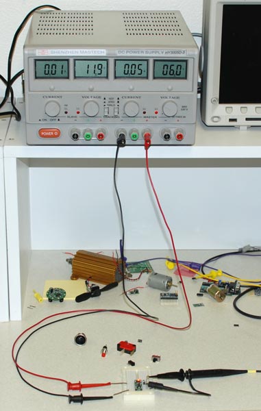 |
LC spike test setup showing bench power supply with 36" power leads. |
|---|
We conducted our tests both with mechanical switches and with the Pololu pushbutton power switch, and we later replaced the power supply with a battery and shorter leads.
Related products


Home | Forum | Blog | Support | Ordering Information | Lists | Distributors | BIG Order Form | About | Contact
© 2001–2026 Pololu Corporation
