

This is a merged information page for Item #2457.
View normal product page.
Pololu item #:
2457
Brand:
Pololu
Status:
Active and Preferred

This compact module packs three IR LED/phototransistor pairs onto a 1.25″ × 0.3″ board. The sensors are mounted on a 0.375″ pitch, allowing this array to be used as a minimal detector for a line-following robot. Each sensor provides a separate digital I/O-measurable voltage output.
 Compare all products in Older QTR Sensors.
 |
QTR-3RC reflectance sensor array. |
|---|
 |
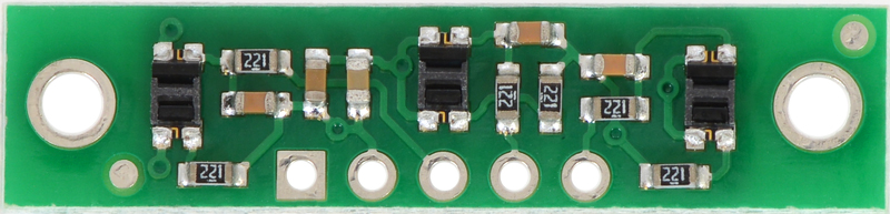
QTR-3A or QTR-3RC reflectance sensor array, bottom view with dimensions. |
|---|
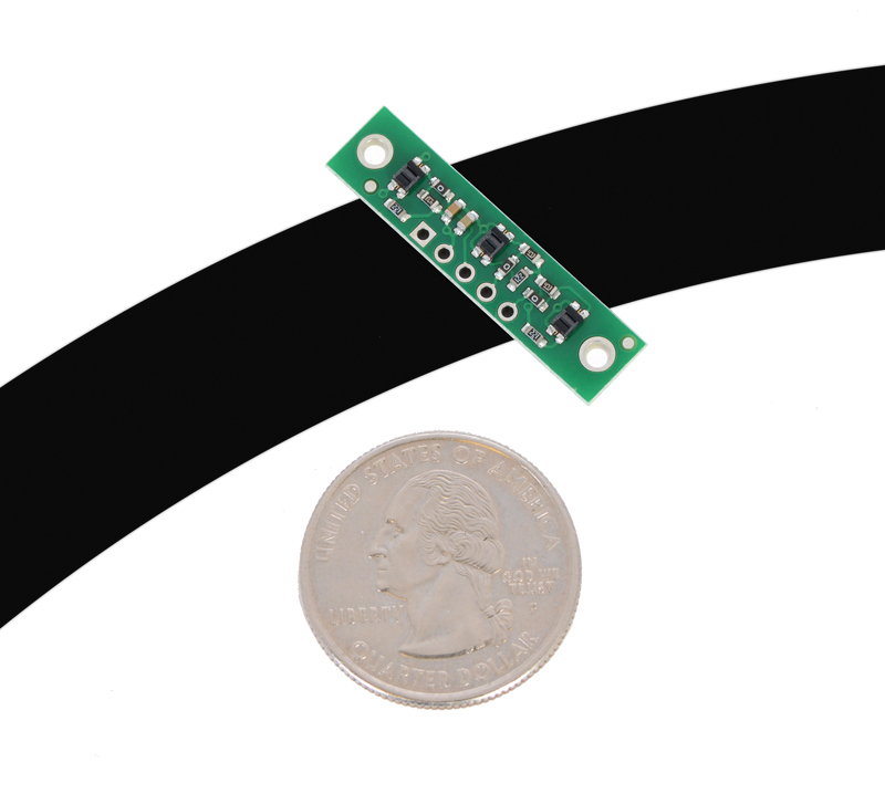 |
QTR-3A or QTR-3RC reflectance sensor array on a 3/4" line with a quarter for size reference. |
|---|
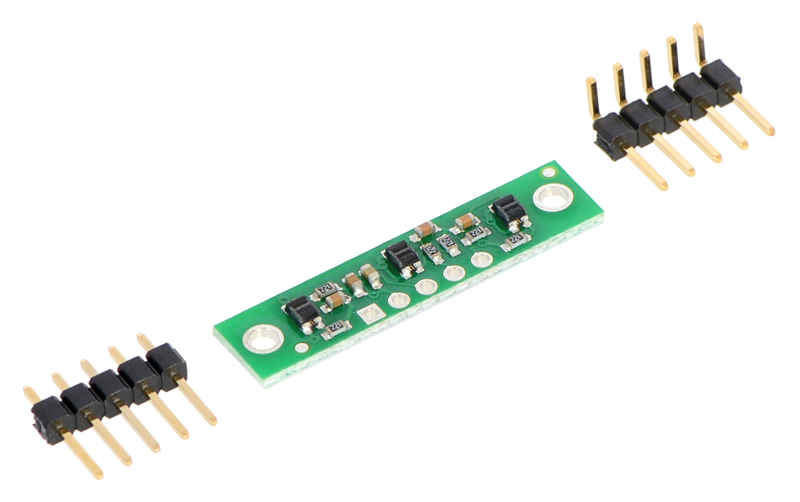 |
QTR-3A or QTR-3RC reflectance sensor array with included header pins. |
|---|
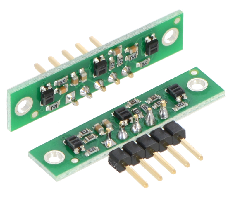 |
QTR-3A and QTR-3RC reflectance sensor arrays soldered in different orientations. |
|---|
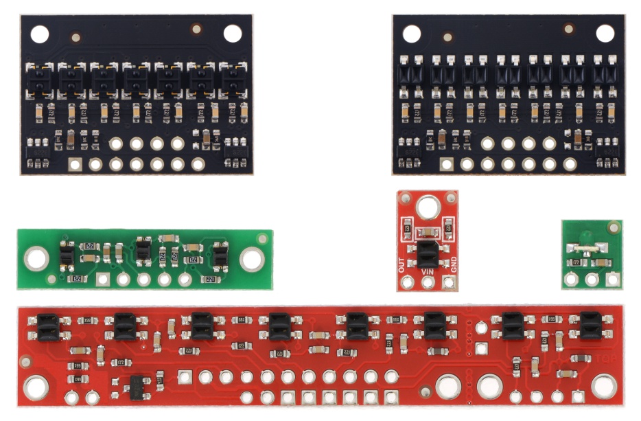 |
QTR sensor size comparison. Top row: QTRX-HD-07, QTR-HD-07; middle row: QTR-3, QTR-1, QTR-L-1; bottom row: QTR-8. |
|---|
 |
Schematic diagram for the QTR-3RC reflectance sensor array. |
|---|
The QTR-3RC reflectance sensor array requires digital I/O lines to take readings. The similar QTR-3A reflectance sensor array is available with analog outputs.
|
The QTR-3RC reflectance sensor array is intended as a line sensor, but it can be used as a general-purpose proximity or reflectance sensor. The module is a convenient carrier for three IR emitter and receiver (phototransistor) pairs. With sensors spaced at intervals of 0.375″ (9.525 mm) along of the board’s longer axis, this array works well as a minimal detector for line-following robots, as line-following courses are commonly made using 3/4″ (19 mm) black electrical tape. The middle sensor is slightly offset along the short axis of the board.
To use a sensor, you must first charge the output node by applying a voltage to its OUT pin. You can then read the reflectance by withdrawing that externally applied voltage on the OUT pin and timing how long it takes the output voltage to decay due to the integrated phototransistor. Shorter decay time is an indication of greater reflection. This measurement approach has several advantages, especially when multiple units are used:
The LED current-limiting resistors are set to deliver approximately 17 mA to the LEDs when VCC is 5 V, making the total board consumption just over 50 mA. The schematic diagram of the module is shown below:
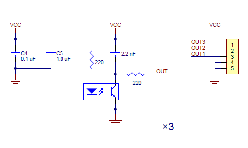 |
This schematic is also available as a downloadable pdf (117k pdf).
For an alternative array with eight sensors and the ability to turn off the IR LEDs to limit power consumption, consider our QTR-8RC reflectance sensor array. For individual reflectance sensors, consider our QTR-1RC and QTR-L-1RC.
|
QTR sensor size comparison. Top row: QTRX-HD-07, QTR-HD-07; middle row: QTR-3, QTR-1, QTR-L-1; bottom row: QTR-8. |
|---|
|
The QTR-3RC module has three identical sensor outputs that, like the Parallax QTI, require a digital I/O line capable of driving the output line high and then measuring the time for the output voltage to decay. The typical sequence for reading a sensor is:
These steps can typically be executed in parallel on multiple I/O lines.
With a strong reflectance, the decay time can be as low as several dozen microseconds; with no reflectance, the decay time can be up to a few milliseconds. The exact time of the decay depends on your microcontroller’s I/O line characteristics. Meaningful results can be available within 1 ms in typical cases (i.e. when not trying to measure subtle differences in low-reflectance scenarios), allowing up to 1 kHz sampling of all three sensors.
Our Pololu AVR library provides functions that make it easy to use these sensors with our Orangutan robot controllers; please see the QTR Reflectance Sensors section of our library command reference for more information. We also have a Arduino library for these sensors.
This module has two mounting holes intended for #2 screws (not included); if the mounting holes are not needed, the ends of the PCB can be ground off to make the unit even smaller (less than 1″ wide). The reflectance sensor array ships with a 1×5 straight male header strip and a1×5 right-angle male header strip as shown below. You can also solder wires, such as ribbon cable, directly to the pads for the smallest installation.
|
|
For more information about how this sensor works, see the “How it works in detail” section of the QTR-1RC product page.
| Size: | 1.25″ × 0.3″1 |
|---|---|
| Weight: | 0.6 g2 |
| Supply current: | 50 mA |
|---|
| PCB dev codes: | irs07a |
|---|---|
| Other PCB markings: | 0J7448 |
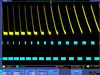
Information about using the Pololu QTR reflectance sensors, including differences between A-type and RC-type sensors and sample oscilloscope screen captures of sensor outputs.

Information about installing and using the C/C++ libraries provided for use with Pololu products.

A reference to commands provided in the Pololu C/C++ and Arduino libraries for the AVR.

Step-by-step instructions for building your own line-following courses.
Printable schematic diagram for the QTR-3RC reflectance sensor array.
Datasheet for the sensor used on the QTR-3RC and QTR-3A Reflectance Sensor Arrays, the Zumo 32U4 robot front sensor array, and the Optical Encoders for micro metal gearmotors.
Un guide utiliser et exploiter un senseur QTR (détecteur de ligne) (version 0.1). Note: This French translation of our QTR sensor documentation was made by our distributor MCHobby.
Matthew Phillipps ported our Arduino Library for the Pololu QTR Reflectance Sensors to the mbed platform. The Arduino library is designed to work with Pololu QTR reflectance sensors, so the mbed library should too, but Matthew points out he only tested it with the analog sensors. This library was not written and is not maintained by Pololu.
This library for Arduino makes it easy to interface with Pololu QTR Reflectance Sensors.
No FAQs available.
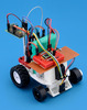
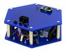
Many of the engineers and robot enthusiasts here at Pololu competed in the LVBots 2015 line following competition. (For house rules and details...
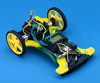
Like other developers and engineers here, I made a robot for the LVBots Line Following Contest. This post describes my robot, Usain Volt 2.0, and...
Several people here made robots to compete in the recent LVBots line following competition. The goal of the competition is to make an autonomous...
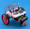
Several Pololu employees made robots for the LVBots dead reckoning competition. Unfortunately, my robot didn’t work enough in time for the...
Like other engineers here, I made a robot for the LVBots dead reckoning competition. Before I knew about this competition, I hadn’t made a...

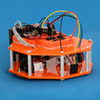
When I first started planning a robot for the recent LVBots dead reckoning competition, it was more or less a conventional design—a flat chassis...
For the recent LVBots dead reckoning competition that was hosted here at Pololu, I decided to make a robot based on the Baby Orangutan robot...
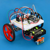
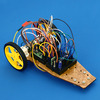
Several people here at Pololu made robots to compete in the LVBots dead reckoning competition last week. This post is about the robot I made along...