

This is a merged information page for Item #5231.
View normal product page.
Pololu item #:
5231
Brand:
Pololu
Status:
Active and Preferred

This is the compact version of a simple carrier for Allegro’s ACS37030LLZATR-040B3 electrically isolated current sensor that uses two signal paths—Hall effect and inductive coil—to capture both low-frequency and high-frequency information. This allows for a DC through 5 MHz bandwidth and typical response times of 40 ns.
| Part Suffix | Range | Supply Voltage | Sensitivity | Zero Point | IC Working Isolation | Size | PCB layers |
|---|---|---|---|---|---|---|---|
| LZ 040B3 | ±40 A (bidirectional) | 3 V to 3.6 V | 33 mV/A | 1.65 V | 840 VRMS | 0.7″×0.8″ | 2 |
Alternatives available with variations in these parameter(s): current range size package Select variant…
 Compare all products in ACS37030 Current Sensor Carriers.
|
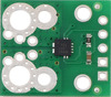
ACS37030LLZ Current Sensor Compact Carrier. |
|---|
 |
ACS37030LLZ Current Sensor Compact Carrier. |
|---|
 |
ACS37030LLZ Current Sensor Compact Carrier pinout. |
|---|
 |
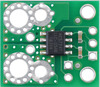
ACS37030LLZATR-040B3 Current Sensor Compact Carrier -40A to +40A, 3.3V, bottom view. |
|---|
 |
ACS37030LLZ Current Sensor Compact Carrier (top) and Large Carrier (bottom) size comparison. |
|---|
 |
ACS37030LLZ Current Sensor Compact Carrier basic hole dimensions. |
|---|
 |
ACS37030LLZ Current Sensor Compact Carrier, top view. |
|---|
 |
ACS37030 Current Sensor Carrier schematic diagram. |
|---|
 |
 |
ACS37030 Current Sensor Carrier family size comparison. |
|---|
We are offering these breakout boards with support from Allegro Microsystems as an easy way to use or evaluate their ACS37030 DC to 5 MHz bandwidth, galvanically isolated, high-accuracy current sensors with reference output; we therefore recommend careful reading of the ACS37030 datasheet (2MB pdf) before using this product. The following list details some of the sensor’s key features:
The connection points are labeled on the silkscreen, which is on the bottom side of the compact versions and on both sides of the large versions. The bottom silkscreen also shows the direction that is interpreted as positive current flow via the +i arrow.
The following table lists the available ACS37030 carrier options:
| Pololu Item # |
Part Suffix | Isolation Rating 1 |
Current Range |
Sensitivity (mV/A) |
Size | PCB Details |
Min PCB Creepage 2 |
Price | |
|---|---|---|---|---|---|---|---|---|---|
 ACS37030LZ Compact Carrier |
#5230 | 020B3 | 840 VRMS | ±20 A | 66 | 0.7″×0.8″ | 2 layers, 2-oz copper |
4.1 mm | $11.95 |
| #5231 | 040B3 | ±40 A | 33 | ||||||
| #5232 | 065B3 | ±65 A | 20.3 | ||||||
 ACS37030LZ Large Carrier |
#5234 | 040B3 | 840 VRMS | ±40 A | 33 | 1.4″×1.2″ | 6 layers, 2-oz copper |
4.1 mm | $14.95 |
| #5235 | 065B3 | ±65 A | 20.3 | ||||||
 ACS37030MY Compact Carrier |
#5694 | 025B3 | 1000 VRMS | ±25 A | 52.8 | 0.8″×1.1″ | 2 layers, 2-oz copper |
11.7 mm | $12.95 |
| #5695 | 040B3 | ±40 A | 33 | ||||||
| #5696 | 065B3 | ±65 A | 20.3 | ||||||
 ACS37030MY Large Carrier |
#5698 | 040B3 | 1000 VRMS | ±40 A | 33 | 1.4″×1.2″ | 6 layers, 2-oz copper |
11.9 mm | $17.95 |
| #5699 | 065B3 | ±65 A | 20.3 | ||||||
| Note 1: IC component rating for basic isolation per manufacturer datasheet. The overall carrier is not certified to any particular safety standard. | |||||||||
| Note 2: Minimum creepage along PCB surface based on layout design only. Other creepage distances, e.g. along the body of the component, may be lower. | |||||||||
Alternatives available with variations in these parameter(s): current range size package Select variant…
|
|
This compact carrier features the ACS37030LLZATR-040B3, which is intended for nominal 3.3 V operation and is designed for bidirectional input current from -40 A to +40 A. This version can be visually distinguished from the other compact ACS37030LZ carriers by the “40” printed on the bottom side, as shown in the left picture above.
| Part Suffix | Range | Supply Voltage | Sensitivity | Zero Point | IC Working Isolation | Size | PCB layers |
|---|---|---|---|---|---|---|---|
| LZ 040B3 | ±40 A (bidirectional) | 3 V to 3.6 V | 33 mV/A | 1.65 V | 840 VRMS | 0.7″×0.8″ | 2 |
A larger carrier with a 6-layer PCB is also available for this sensor IC with room for larger connectors and thicker wires for the high-current path, offering different ways to use or evaluate this current sensor.
|
This sensor has five required connections: the input current (IP+ and IP-), logic power (VDD and GND), and the sensor output (VOUT).
The sensor requires a supply voltage of 3.0 V to 3.6 V to be connected across the VDD and GND pads, which are labeled on the bottom silkscreen. The sensor outputs an analog voltage on VOUT that is centered at 1.65 V and changes by 33 mV per amp of input current, with positive current increasing the output voltage and negative current decreasing the output voltage:
``V_"OUT" = 1.65 text(V) + 0.033 text(V)/text(A) * I_"P"``
``I_"P" = (V_"OUT" – 1.65 text(V)) / (0.033 text(V)/text(A)) = (V_"OUT" – 1.65 text(V)) * 30.3 text(A)/text(V)``
The output is not ratiometric, so the zero point and sensitivity are independent of the actual supply voltage.
The zero-current reference voltage, which is available on VREF, can be used to reduce errors due to reference shifts or noise on the ground line.
|
You can insert the board into your current path in a variety of ways. For typical high-current applications, you can solder wires directly to the through-holes that best match your wires, or you can use solderless ring terminal connectors. The largest through-holes are big enough for 10 AWG wires or #6 or M3.5 screws, and the second-largest through-holes (and mounting holes) are sized for 14 AWG wires or #2 or M2 screws. Holes with 0.1″, 3.5 mm, and 5 mm spacing are also available as shown in the diagram above for connecting male header pins or terminal blocks, but please note that these connection options are generally not suitable for high currents and could limit the usable range of the sensor. The pictures below show examples of various connection options with the ACS37220 compact carrier, which has the same physical dimensions as the ACS37030LLZ compact carrier.
|
|
||
|
|
The VREF, VOUT, VDD, and GND pins work with 0.1″-pitch header pins and are compatible with standard solderless breadboards
The ACS37030LLZ and ACS37030LMY differ in their manufacturer-rated isolation voltages of 840 VRMS and 1000 VRMS, respectively. The PCB creepage on the ACS37030LLZ carriers is 4.1 mm, which is the same as the creepage on the LZ IC package itself. The MY IC package has a wider body with a creepage of 8.5 mm, and our ACS37030LMY compact carrier PCB has a routed slot under the IC to provide a PCB creepage of 11.7 mm. A rough rule of thumb is that uncontaminated FR4 PCBs should have roughly 1 mm of creepage per 100 VRMS of isolation. Please note that these carrier boards are not certified to any particular safety standard.
Warning: This product is generally intended for use below 30 V, and many of the application example pictures (e.g. use on a breadboard) are appropriate for such lower-voltage applications. These boards can be used at higher voltages, but working with higher voltages can be extremely dangerous and should only be attempted by qualified individuals with appropriate equipment and experience.
|
ACS37030 Current Sensor Carrier schematic diagram. |
|---|
The dimension diagram is available as a downloadable PDF (1MB pdf).
 |
Thermal image of a high-current test of a Pololu current sensor carrier (not necessarily this product). |
|---|
Depending on the version, the ACS37030 can measure up to ±65 A. However, the sensor chip can overheat at lower currents. In our tests, we found that our ACS37030LLZ compact carrier boards could conduct about 55 A continuously without reaching the thermal limit for the IC. Our tests were conducted at approximately 25°C ambient temperature with no forced air flow.
The actual current you can pass through the sensor will depend on how well you can keep it cool. The carrier’s printed circuit board is designed to help with this by drawing heat out of the sensor chip. Solid connections to the current path pins (such as with thick soldered wires or large, tightly-secured lugs) can also help reduce heat build-up in the sensor and carrier board, as can switching to the equivalent large carrier version.
Warning: Exceeding temperature or current limits can cause permanent damage to the sensor. If you are measuring an average continuous current greater than 45 A, we strongly recommend that you monitor the sensor’s temperature and look into additional cooling if necessary.
This product can get hot enough to burn you long before the chip overheats. Take care when handling this product and other components connected to it.
We have a variety of current sensors available with different ranges, sensitivities, and features. The table below summarizes our selection of active and preferred options:
 |
 |
 |
 |
 |
 |
 |
 |
 |
 |
|
|---|---|---|---|---|---|---|---|---|---|---|
| CT220 Contactless Current Sensor Carriers |
ACS3704x Current Sensor Micro Carriers |
ACS3704x Current Sensor Compact Carriers |
ACS711 Current Sensor Carriers |
ACS71240 Current Sensor Carriers |
ACS724 Current Sensor Carriers |
ACS37100 TMR Current Sensor Compact Carriers |
ACS37030LZ Current Sensor Compact Carriers |
ACS37030MY Current Sensor Compact Carriers |
CT432/CT433 TMR Current Sensor Compact Carriers |
|
| Allegro Sensor | CT220xMV-HS5 | ACS3704x | ACS711KEXT | ACS71240 | ACS724LLCTR | ACS37100 | ACS37030LLZ | ACS37030LMY | CT432/CT433 | |
| Sensing technology | XtremeSense™ TMR (tunneling magnetoresistance) |
Hall effect | Hall effect | Hall effect | Hall effect | XtremeSense™ TMR (tunneling magnetoresistance) |
Hall effect + inductive coil | XtremeSense™ TMR (tunneling magnetoresistance) |
||
| Logic voltage range | 2.7–5.5 V | 3.3V versions: 3.0–3.6 V 5V versions: 4.75–5.5 V |
3.0–5.5 V | 3.3V ver: 3.0–3.6 V 5V ver: 4.5–5.5 V |
4.5–5.5 V | 3.0–3.6 V | 3.0–3.6 V | 3.3V ver: 3.0–3.6 V 5V ver: 4.75–5.5 V |
||
| Family current range | 10–800 A | 10–30 A | 15.5–31 A | 10–50 A | 2.5–50 A | 25–50 A | 20–65 A | 20–70 A | ||
| Range/sensitivity of individual versions | (2) ±1.5 mT / 1500 mV/mT ±15 mT / 150 mV/mT |
ACS37041: 3.3V Bidirectional: ±10 A / 132 mV/A ±30 A / 44 mV/A 5V Bidirectional: ±10 A / 200 mV/A ±30 A / 66.7 mV/A ACS37042: 3.3V Bidirectional: ±10 A / 132 mV/A ±30 A / 44 mV/A 5V Bidirectional: ±10 A / 200 mV/A ±30 A / 66.7 mV/A |
ACS37041: 3.3V Bidirectional: ±10 A / 132 mV/A ±30 A / 44 mV/A 5V Bidirectional: ±10 A / 200 mV/A ±30 A / 66.7 mV/A ACS37042: 3.3V Bidirectional: ±10 A / 132 mV/A ±30 A / 44 mV/A 5V Bidirectional: ±10 A / 200 mV/A ±30 A / 66.7 mV/A |
Bidirectional:(1) ±15.5 A / 90 mV/A ±31 A / 45 mV/A |
3.3V Bidirectional: ±10 A / 132 mV/A ±30 A / 44 mV/A ±50 A / 26.4 mV/A 5V Bidirectional: ±10 A / 200 mV/A ±30 A / 66 mV/A ±50 A / 40 mV/A 5V Unidirectional: 0–50 A / 80 mv/A |
5V Bidirectional:(2) ±2.5 A / 800 mV/A ±5 A / 400 mV/A ±10 A / 200 mV/A ±20 A / 100 mV/A ±30 A / 66 mV/A ±50 A / 40 mV/A 5V Unidirectional:(2) 0–5 A / 800 mv/A 0–10 A / 400 mv/A 0–20 A / 200 mv/A 0–30 A / 133 mV/A |
3.3V Bidirectional: ±25 A / 52.8 mV/A ±50 A / 26.4 mV/A |
3.3V Bidirectional: ±20 A / 66 mV/A ±40 A / 33 mV/A ±65 A / 20.3 mV/A |
3.3V Bidirectional: ±20 A / 66 mV/A ±40 A / 33 mV/A ±65 A / 20.3 mV/A |
3.3V Bidirectional: ±20 A / 50 mV/A ±30 A / 33.3 mV/A ±50 A / 20 mV/A ±70 A / 14.3 mV/A 3.3V Unidirectional: 0–20 A / 100 mv/A 0–30 A / 66.7 mv/A 0–50 A / 40 mv/A 0–65 A / 30.8 mv/A 5V Bidirectional: ±20 A / 100 mV/A ±30 A / 66.7 mV/A ±50 A / 40 mV/A ±65 A / 30.8 mV/A 5V Unidirectional: 0–20 A / 200 mv/A 0–30 A / 133.3 mv/A 0–50 A / 80 mv/A 0–70 A / 57.1 mv/A |
| Max bandwidth | 30 kHz | 150 kHz | 100 kHz | 120 kHz | 120 kHz(3) | 10 MHz | 5 MHz | 1 MHz | ||
| IC current path resistance | N/A (contactless) | 1.6 mΩ | 0.6 mΩ | 0.6 mΩ | 0.6 mΩ | 1.2 mΩ | 0.7 mΩ | 0.9 mΩ | 1 mΩ | |
| IC isolation rating(6) | N/A (contactless) | ACS37041: 100 VRMS ACS37042: 285 VRMS |
100 Vpk | 100 Vpk | 297 VRMS | 1097 VRMS | 840 VRMS | 1000 VRMS | 1100 VRMS | |
| Minimum PCB creepage(7) | N/A (contactless) | ACS37041: 1.6 mm ACS37042: 2.0 mm |
ACS37041: 1.6 mm ACS37042: 3.0 mm |
0.75 mm | 0.75 mm | 1.1 mm | 9.3 mm | 4.1 mm | 11.7 mm | 8 mm |
| PCB | N/A (contactless) | 2 layers, 1-oz copper |
2 layers, 2-oz copper |
2 layers, 2-oz copper |
2 layers, 2-oz copper |
2 layers, 2- or 4-oz copper(4) |
2 layers, 2-oz copper |
2 layers, 2-oz copper |
2 or 4 layers(5), 2-oz copper |
|
| Size | 0.4″ × 0.62″ | 0.3″ × 0.4″ | 0.7″ × 0.8″ | 0.7″ × 0.8″ | 0.7″ × 0.8″ | 0.7″ × 0.8″ | 0.8″ × 1.1″ | 0.7″ × 0.8″ | 0.8″ × 1.1″ | 0.8″ × 1.1″ |
| Overcurrent fault output |
(configurable threshold) | |||||||||
| Common-mode field rejection | ||||||||||
| Nonratiometric output | ||||||||||
| 1-piece price | $4.95 | $4.15 – $4.69 | $4.45 – $4.99 | $4.85 | $5.25 | $9.95 – $11.49 | $14.95 | $11.95 | $12.95 | $12.95 |
Note 1: Sensitivity when Vcc = 3.3 V; actual sensitivity is ratiometric (i.e. it is proportional to Vcc).
Note 2: Sensitivity when Vcc = 5 V; actual sensitivity is ratiometric (i.e. it is proportional to Vcc).
Note 3: Bandwidth can be reduced by adding a filter capacitor.
Note 4: 50A version of this carrier uses 4-oz copper PCB; all other versions of this carrier use 2-oz copper.
Note 5: 50A and higher versions of this carrier use a 4-layer PCB; all other versions of this carrier use a 2-layer PCB.
Note 6: IC component rating per manufacturer datasheet.
Note 7: Minimum creepage along PCB surface based on layout design only. Other creepage distances, e.g. along the body of the component, may be lower.
|
 |
|
 |
|
 |
 |
 |
 |
 |
|
|---|---|---|---|---|---|---|---|---|---|---|
| ACS37030LZ Current Sensor Compact Carriers |
ACS37030LZ Current Sensor Large Carriers |
ACS37030MY Current Sensor Compact Carriers |
ACS37030MY Current Sensor Large Carriers |
CT432/CT433 TMR Current Sensor Compact Carriers |
CT432/CT433 TMR Current Sensor Large Carriers |
ACS72981 Current Sensor Compact Carriers |
ACS72981 Current Sensor Large Carriers |
ACS37220 Current Sensor Compact Carriers |
ACS37220 Current Sensor Large Carriers |
|
| Allegro Sensor | ACS37030LLZ | ACS37030LMY | CT432/CT433 | ACS72981xLR | ACS37220 | |||||
| Sensing technology | Hall effect + inductive coil | XtremeSense™ TMR (tunneling magnetoresistance) |
Hall effect | Hall effect | ||||||
| Logic voltage range | 3.0–3.6 V | 3.3V versions: 3.0–3.6 V 5V versions: 4.75–5.5 V |
3.3V versions: 3.0–3.6 V 5V versions: 4.5–5.5 V |
3.3V versions: 3.15–3.45 V 5V versions: 4.5–5.5 V |
||||||
| Family current range | 20–65 A | 20–70 A | 50–200 A | 100–200 A | ||||||
| Range/sensitivity of individual versions | 3.3V Bidirectional: ±20 A / 66 mV/A ±40 A / 33 mV/A ±65 A / 20.3 mV/A |
3.3V Bidirectional: ±40 A / 33 mV/A ±65 A / 20.3 mV/A |
3.3V Bidirectional: ±25 A / 52.8 mV/A ±40 A / 33 mV/A ±65 A / 20.3 mV/A |
3.3V Bidirectional: ±40 A / 33 mV/A ±65 A / 20.3 mV/A |
3.3V Bidirectional: ±20 A / 50 mV/A ±30 A / 33.3 mV/A ±50 A / 20 mV/A ±70 A / 14.3 mV/A 3.3V Unidirectional: 0–20 A / 100 mv/A 0–30 A / 66.7 mv/A 0–50 A / 40 mv/A 0–65 A / 30.8 mv/A 5V Bidirectional: ±20 A / 100 mV/A ±30 A / 66.7 mV/A ±50 A / 40 mV/A ±65 A / 30.8 mV/A 5V Unidirectional: 0–20 A / 200 mv/A 0–30 A / 133.3 mv/A 0–50 A / 80 mv/A 0–70 A / 57.1 mv/A |
3.3V Bidirectional: ±50 A / 20 mV/A ±70 A / 14.3 mV/A 3.3V Unidirectional: 0–50 A / 40 mv/A 0–65 A / 30.8 mv/A 5V Bidirectional: ±50 A / 40 mV/A ±65 A / 30.8 mV/A 5V Unidirectional: 0–50 A / 80 mv/A 0–70 A / 57.1 mv/A |
3.3V Bidirectional:(1) ±50 A / 26.4 mV/A ±100 A / 13.2 mV/A ±150 A / 8.8 mV/A ±200 A / 6.6 mV/A 3.3V Unidirectional:(1) 0–50 A / 52.8 mv/A 0–100 A / 26.4 mv/A 0–150 A / 17.6 mv/A 0–200 A / 13.2 mv/A 5V Bidirectional:(2) ±50 A / 40 mV/A ±100 A / 20 mV/A ±150 A / 13.3 mV/A ±200 A / 10 mV/A 5V Unidirectional:(2) 0–50 A / 80 mv/A 0–100 A / 40 mv/A 0–150 A / 26.7 mv/A |
3.3V Bidirectional:(1) ±50 A / 26.4 mV/A ±100 A / 13.2 mV/A ±150 A / 8.8 mV/A ±200 A / 6.6 mV/A 3.3V Unidirectional:(1) 0–50 A / 52.8 mv/A 0–100 A / 26.4 mv/A 0–150 A / 17.6 mv/A 0–200 A / 13.2 mv/A 5V Bidirectional:(2) ±50 A / 40 mV/A ±100 A / 20 mV/A ±150 A / 13.3 mV/A ±200 A / 10 mV/A 5V Unidirectional:(2) 0–50 A / 80 mv/A 0–100 A / 40 mv/A 0–150 A / 26.7 mv/A |
3.3V Bidirectional: ±100 A / 13.2 mV/A ±150 A / 8.8 mV/A 5V Bidirectional: ±100 A / 20 mV/A ±150 A / 13.3 mV/A ±200 A / 10 mV/A |
3.3V Bidirectional: ±100 A / 13.2 mV/A ±150 A / 8.8 mV/A 5V Bidirectional: ±100 A / 20 mV/A ±150 A / 13.3 mV/A ±200 A / 10 mV/A |
| Max bandwidth | 5 MHz | 1 MHz | 250 kHz | 150 kHz | ||||||
| IC current path resistance | 0.7 mΩ | 0.9 mΩ | 1 mΩ | 0.2 mΩ | 0.1 mΩ | |||||
| IC isolation rating(4) | 840 VRMS | 1000 VRMS | 1100 VRMS | 100 Vpk | 100 VRMS | |||||
| Minimum PCB creepage(5) | 4.1 mm | 11.7 mm | 11.9 mm | 8 mm | 1.1 mm | 1.0 mm | ||||
| PCB | 2 layers, 2-oz copper |
6 layers, 2-oz copper |
2 layers, 2-oz copper |
6 layers, 2-oz copper |
2 or 4 layers(3), 2-oz copper |
6 layers, 2-oz copper |
6 layers, 2-oz copper |
6 layers, 2-oz copper |
2 layers, 2-oz copper |
6 layers, 2-oz copper |
| Size | 0.7″ × 0.8″ | 1.4″ × 1.2″ | 0.8″ × 1.1″ | 1.4″ × 1.2″ | 0.8″ × 1.1″ | 1.4″ × 1.2″ | 0.7″ × 0.8″ | 1.4″ × 1.2″ | 0.7″ × 0.8″ | 1.4″ × 1.2″ |
| Overcurrent fault output |
(configurable threshold) | |||||||||
| Common-mode field rejection | ||||||||||
| Nonratiometric output | ||||||||||
| 1-piece price | $11.95 | $14.95 | $12.95 | $17.95 | $12.95 | $16.95 | $13.95 | $16.95 | $6.95 | $10.95 |
Note 1: Sensitivity when Vcc = 3.3 V; actual sensitivity is ratiometric (i.e. it is proportional to Vcc).
Note 2: Sensitivity when Vcc = 5 V; actual sensitivity is ratiometric (i.e. it is proportional to Vcc).
Note 3: 50A and higher versions of this carrier use a 4-layer PCB; all other versions of this carrier use a 2-layer PCB.
Note 4: IC component rating per manufacturer datasheet.
Note 5: Minimum creepage along PCB surface based on layout design only. Other creepage distances, e.g. along the body of the component, may be lower.
You can also use the following selection box to see these options sorted by current range:
Alternatives available with variations in these parameter(s): current range Select variant…
| Size: | 0.7″ × 0.8″ |
|---|---|
| Weight: | 1.2 g |
| Typical operating voltage: | 3.3 V |
|---|---|
| Current sense: | 33 mV/A |
| Minimum logic voltage: | 3.0 V |
| Maximum logic voltage: | 3.6 V |
| Package: | LZ |
| Working isolation voltage: | 840 VRMS1 |
| Supply current: | 20 mA2 |
| Current range: | -40A to +40A (bidirectional 40A), 3.3V |
| Current sensor: | Allegro ACS37030LLZATR-040B3 |
| PCB dev codes: | cs09a |
|---|---|
| Other PCB markings: | 0J15202 |
| Other PCB markings: | 40 |
This DXF drawing shows the locations of all of the board’s holes.
Allegro product page for the ACS37030, where you can find additional application notes and other resources.
No FAQs available.
No blog posts to show.


