This is a merged information page for Item #3542.
View normal product page.
Pololu item #:
3542
Brand:
Pololu
Status:
Active and Preferred

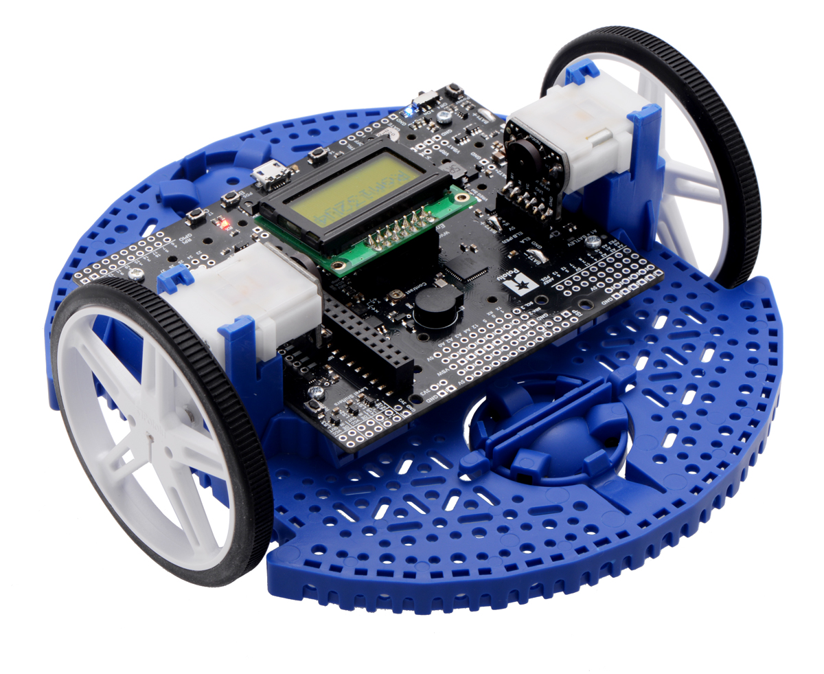
Add quadrature encoders to the mini plastic gearmotors on your Romi chassis with this kit that uses a magnetic disc and Hall effect sensors to provide 12 counts per revolution of the motor shaft. The sensors operate from 3.5 V to 18 V and provide digital outputs that can be connected directly to a microcontroller or other digital circuit.
This kit includes two encoder boards and two magnetic discs.
 Compare all products in Romi Chassis and Accessories or Encoders.
|
Romi Encoder Pair Kit, 12 CPR, 3.5-18V. |
|---|
 |
The motor portion can be removed from the gearbox and rotated 180° to change whether the connector pins point up or down. |
|---|
 |
The motor can be removed from the gearbox even when the encoder is soldered to the motor. |
|---|
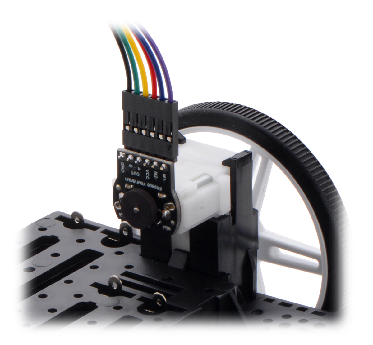 |
The included low-profile headers are still long enough to work with our pre-crimped jumper wires. |
|---|
 |
A standard-length straight 0.1″ male header allows for compact cable connection. |
|---|
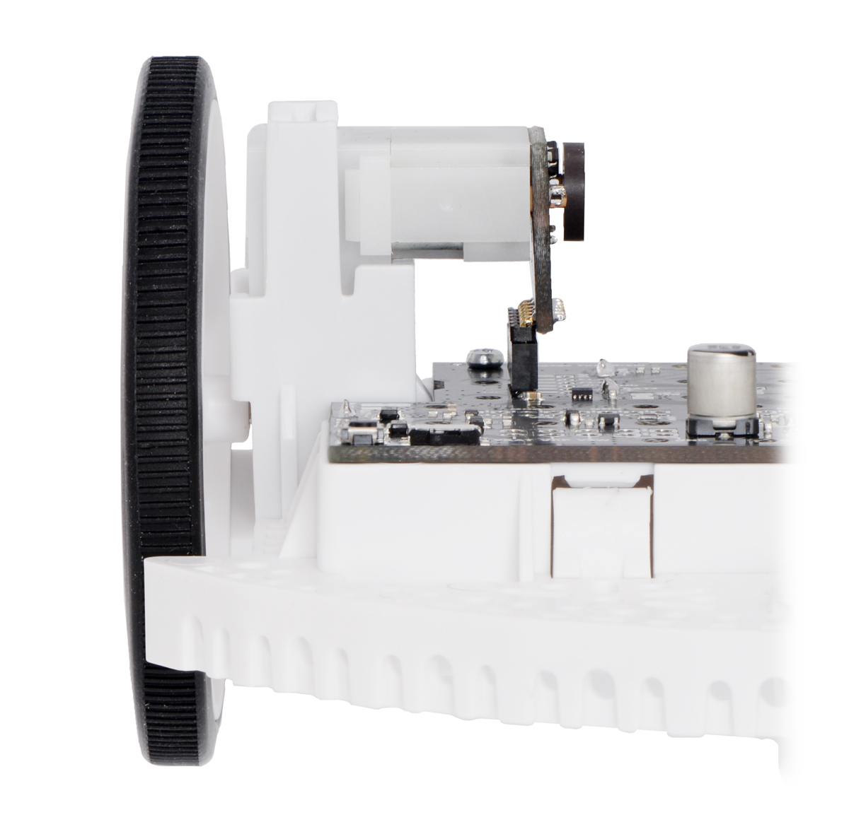 |
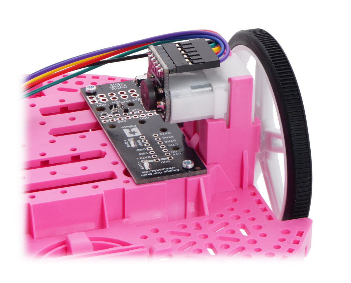
The Romi Encoder can plug directly into the Motor Driver and Power Distribution Board for Romi Chassis. |
|---|
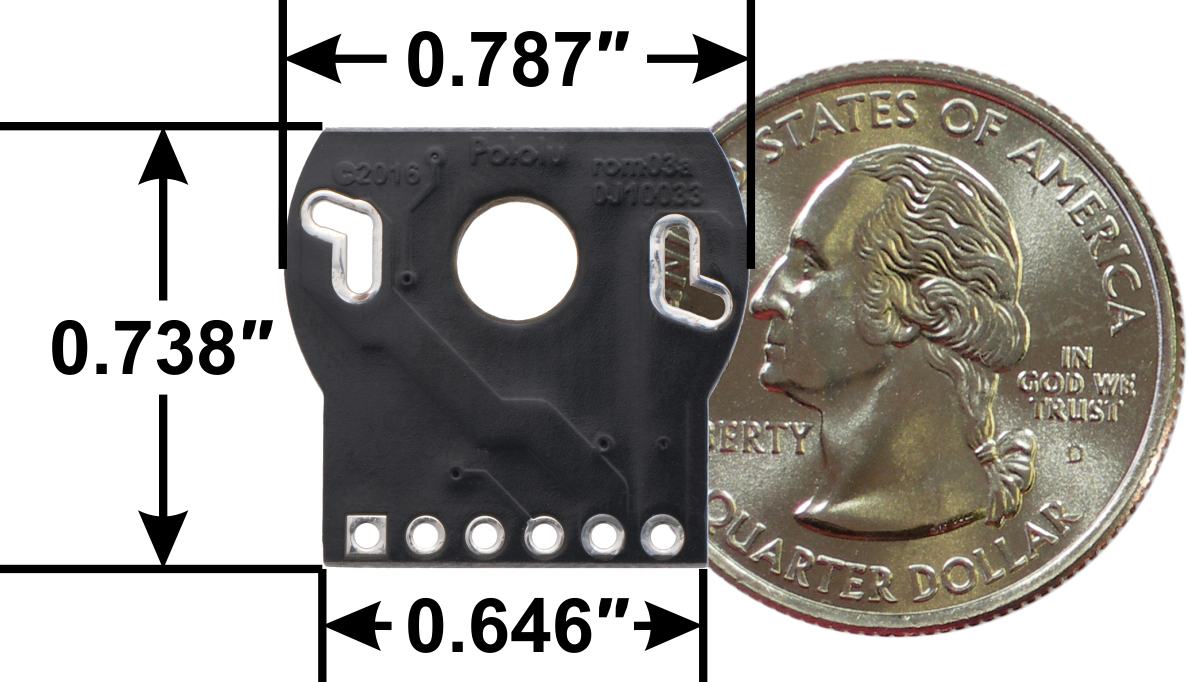 |
Romi Encoder Pair Kit, motor-side view of PCB with dimensions. |
|---|
 |
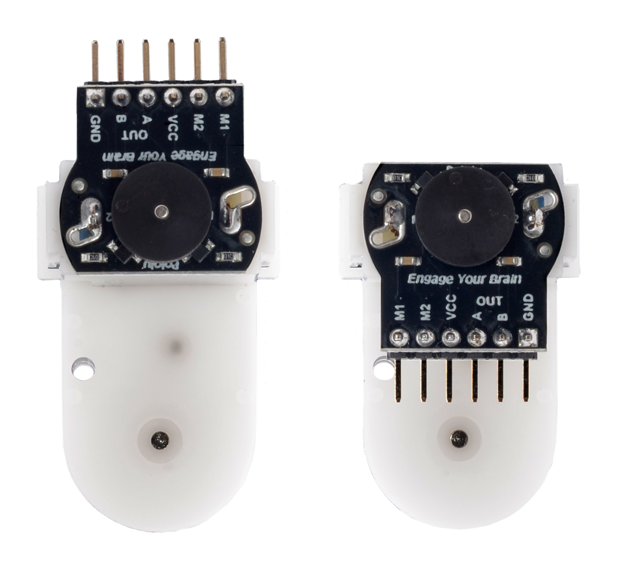
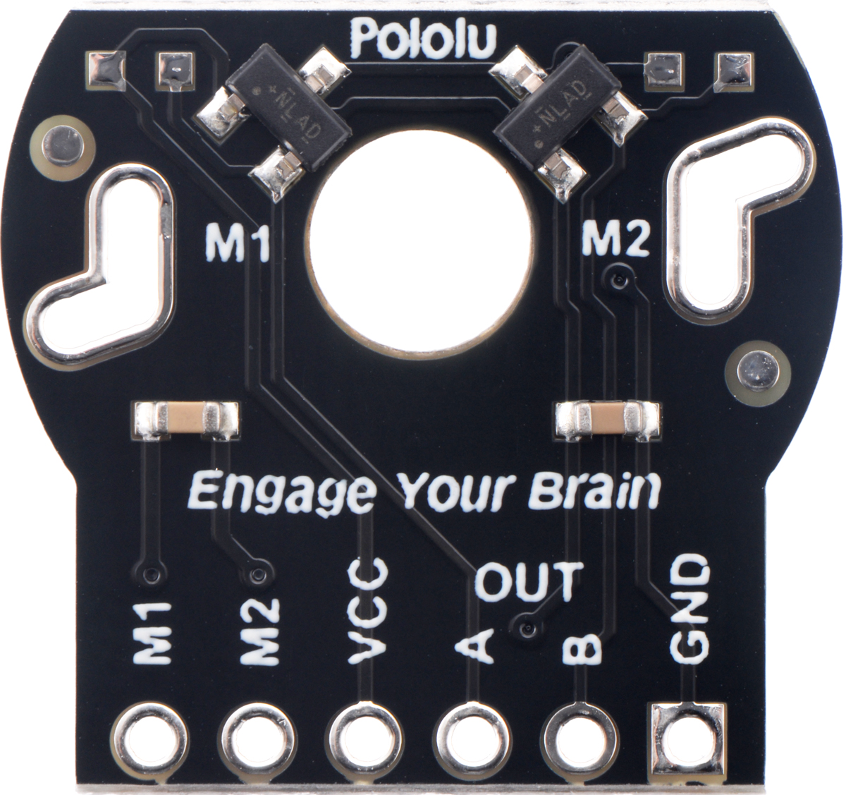
Romi Encoder Pair Kit, magnet-side view of PCB with labeled pinout. |
|---|
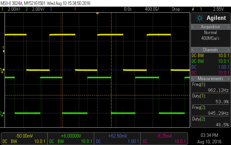 |
Encoder A and B outputs of a magnetic encoder on a high-power (HP) mini plastic gearmotor running at 4.5 V. |
|---|
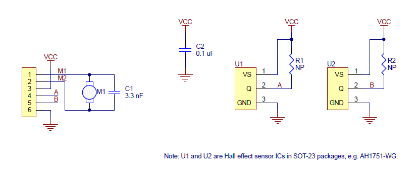 |
Schematic diagram for the Romi Encoder Pair Kit. |
|---|
 |
Romi Encoder Pair Kit, magnet-side view of PCB. |
|---|
 |
Romi Encoder Pair Kit, motor-side view of PCB |
|---|
This kit includes two dual-channel Hall effect sensor boards and two 6-pole magnetic discs that can be used to add quadrature encoding to the mini plastic gearmotors on a Romi chassis. The encoder board senses the rotation of the magnetic disc and provides a resolution of 12 counts per revolution of the motor shaft when counting both edges of both channels, which corresponds to approximately 1440 counts per revolution of the Romi’s wheels.
This compact encoder solution fits within the 11.5 mm × 22.5 mm cross section of the rear of the motors on three of the four sides. The fourth side of the encoder has the signal and power connections, and it extends 7 mm past the edge of the motor so that it is at just the right height to be able to plug into a board mounted below on the Romi chassis when the included low-profile male and female header pins are used. The assembly does not extend past the end of the extended motor shaft, which protrudes 5 mm beyond the back of the motor.
The encoder board is designed to be soldered directly to the back of the motor, with the back shaft of the motor protruding through the hole in the middle of the circuit board. One way to achieve good alignment between the board and the motor is to tack down the board to one motor pin and to solder the other pin only when the board is flat and well aligned. Be careful to avoid prolonged heating of the motor pins, which could deform the motor case or brushes.
We currently have two boards that the these encoders can directly plug into: the Romi 32U4 Control Board and the Motor Driver and Power Distribution Board for Romi Chassis. The encoder pins need to be installed pointing down toward the chassis in order to be able to plug into this board.
|
|
For robots not using these boards, it might be more convenient to install the board and pins facing up and connect to them with a cable made from our wires with pre-crimped terminals.
|
The included low-profile headers are still long enough to work with our pre-crimped jumper wires. |
|---|
To later use the same encoders with a board that they can plug into, just pull the motor portion off of the gearbox, rotate it 180°, and push it back in to make the encoder and pins point down.
|
|
If you do not care about compatibility with existing or potential future boards, we recommend soldering wires directly to the encoder or installing a standard-length male header that works better with cables made from our wires with pre-crimped terminals.
|
A standard-length straight 0.1″ male header allows for compact cable connection. |
|---|
Once the board is soldered down to the two terminals, the motor leads are connected to the M1 and M2 pads along the edge of the board; the remaining four pads are used to power the sensors and access the two quadrature outputs:
|
|
The sensors are powered through the VCC and GND pins. VCC can be 3.5 V to 18 V, and the quadrature outputs A and B are open-drain digital signals that need to be pulled up to the appropriate logic voltage of your system. The encoder boards have pads for optional 0603 size surface-mount resistors to pull the outputs up to VCC, but in typical applications, the pull-up resistors will be on the main electronics board.
|
Encoder A and B outputs of a magnetic encoder on a high-power (HP) mini plastic gearmotor running at 4.5 V. |
|---|
The board’s six through-holes have a 0.1″ (2.54 mm) pitch, so they are compatible with common 0.1″ connectors, or you can just solder individual wires directly to the board.
Once the board is soldered to the motor, the magnetic encoder disc can be pushed onto the motor shaft. One easy way to accomplish this is to press the motor onto the disc while it is sitting on a flat surface, pushing until the shaft makes contact with that surface. The size of the gap between the encoder disc and the sensor board does not have a big impact on performance as long as the motor shaft is at least all the way through the disc.
|
This schematic is also available as a downloadable pdf (88k pdf).
| Size: | 20 mm × 18.7 mm1 |
|---|---|
| Weight: | 3.0 g2 |
| Minimum operating voltage: | 3.5 V |
|---|---|
| Maximum operating voltage: | 18 V |
| PCB dev codes: | rom03a |
|---|---|
| Other PCB markings: | 0J10033 |
This DXF drawing shows the locations of all of the board’s holes.
This file contains 3D models (in the step file format) of the components for the Romi Encoder Pair Kit, 12 CPR, 3.5-18V.
No FAQs available.
Forum user DrGFreeman has been busy making robots. I wrote earlier about his Custom Mini Sumo robot; now here is his Romi Chassis and Raspberry Pi...
What do you need to turn a Romi chassis into a functioning robot? Here are some Romi projects from the community, as well a couple of our example...