This is a merged information page for Item #3615.
View normal product page.
Pololu item #:
3615
Brand:
Concentric

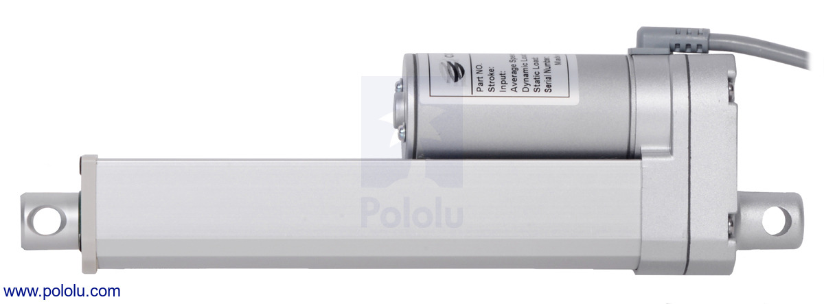
This 12 V medium-duty (MD) linear actuator can lift loads up to 100 kgf [225 lbs or 1000 N] and can withstand static loads up to 450 kgf [1000 lbs or 4500 N]. It has a maximum speed of 14.7 mm/s [0.58″/s] at no load and 10.4 mm/s [0.41″/s] at the maximum load. Limit switches at each end make the actuator easy to control over its full range of motion. The shaft holds its position when unpowered. This version has a 6-inch stroke (5.9″ usable) and a no feedback potentiometer.
Alternatives available with variations in these parameter(s): nominal stroke length feedback potentiometer included? Select variant…
 Compare all products in Glideforce Medium-Duty (MD) Linear Actuators.
 |
Glideforce Medium-Duty (MD) series of linear actuators. |
|---|
 |
Glideforce Medium-Duty (MD) series of linear actuators with feedback. |
|---|
 |
Connectors that terminate the cable ends of Glideforce Medium-Duty (MD) linear actuators with feedback. |
|---|
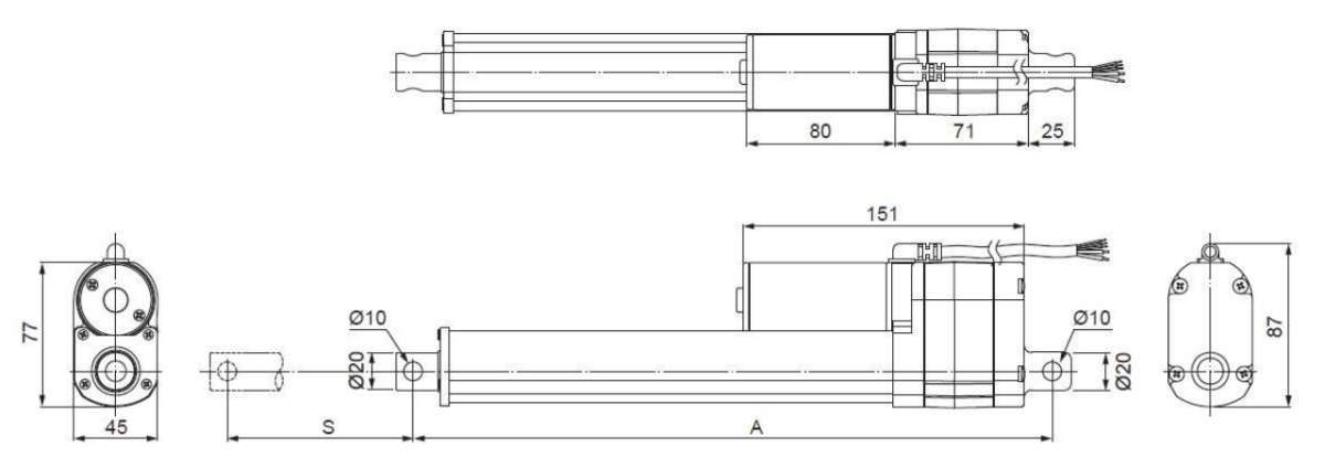 |
Dimensions of Glideforce MD linear actuators with feedback. Units are mm. |
|---|
 |
Glideforce Medium-Duty (MD) series of linear actuators without feedback. |
|---|
 |
Unterminated wire ends for Glideforce Medium-Duty (MD) linear actuators without feedback. |
|---|
 |
Dimensions of Glideforce MD linear actuators without feedback. Units are mm. |
|---|
 |
Glideforce MD122004 medium-duty linear actuator (4″ stroke) with shaft fully extended. |
|---|
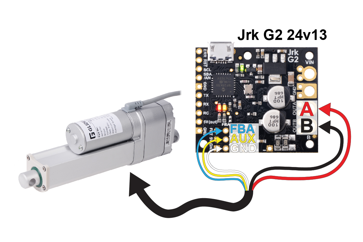 |
Connecting a medium-duty linear actuator with feedback to a Jrk 24v13 motor controller. |
|---|
|
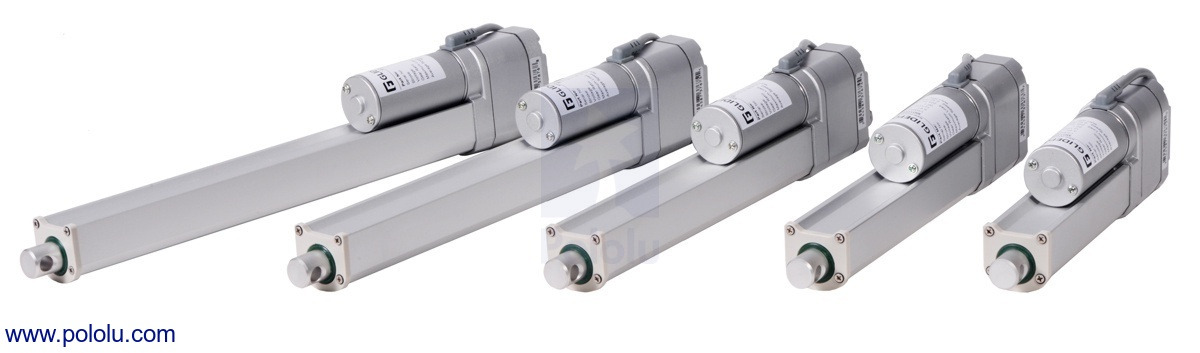
The Medium-Duty (MD) series of Glideforce linear actuators by Concentric International (formerly Iowa Export-Import) are 12V DC gearmotors that use a lead screw to move a shaft back and forth along its length. All of the actuators in this category have a 20:1 gearbox reduction with all metal gears, which allows them to move loads up to 100 kgf [225 lbs or 1000 N] and gives them a maximum speed of between 1.0 and 1.5 cm/s [0.4 and 0.6 in/s], depending on the load. The shaft will hold its position even when unpowered and subjected to static loads up to 450 kgf [1000 lbs or 4500 N]. Two limit switches safely stop the motor at either end of its range, while integrated diodes allow it to reverse direction after reaching a limit point if the supplied voltage is reversed. The actuators have an all-aluminum frame and extension tube, and the entire case is sealed to protect against dust and water (rated IP65).
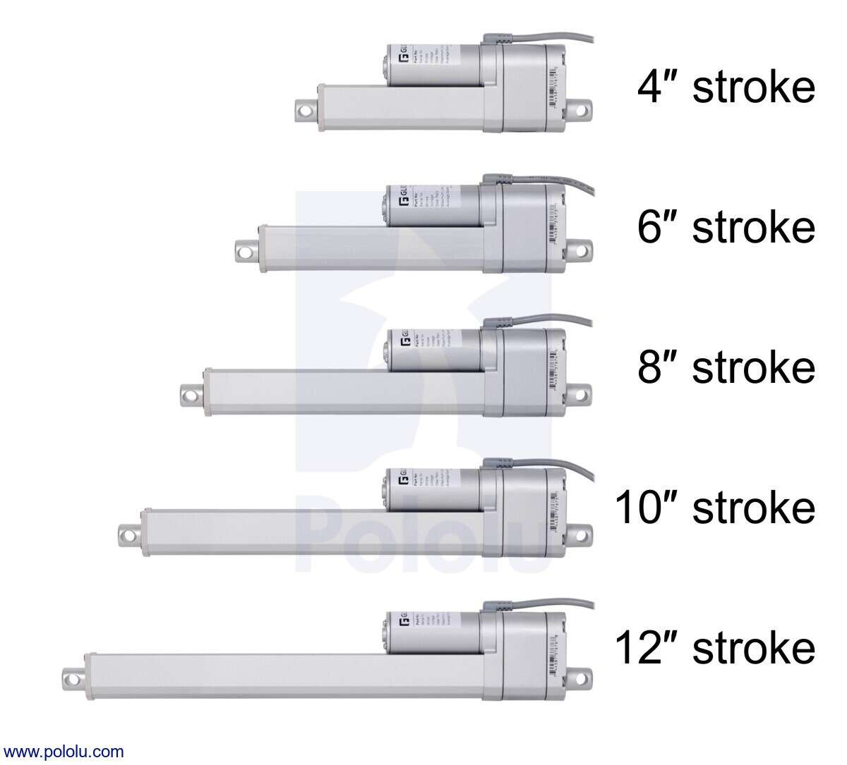
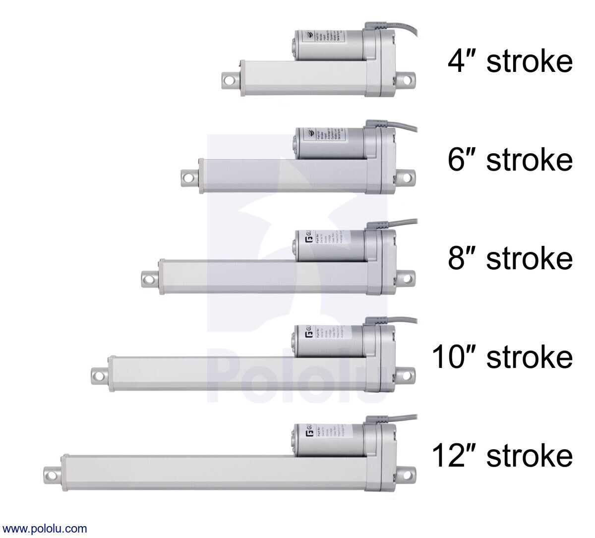
These actuators are available in a variety of stroke lengths, from 4″ to 12″, and with optional potentiometers that are linked to the shaft position, for use in feedback systems:
| Actuator Type |
Max Dynamic Load |
No-Load Speed @ 12 V |
Max-Load Speed @ 12 V |
Current Draw @ 12 V |
Nominal Stroke Length |
With Feedback |
Without Feedback |
|---|---|---|---|---|---|---|---|
| Medium-Duty (MD) |
100 kgf [225 lb] |
1.5 cm/s [0.58″/s] |
1.0 cm/s [0.41″/s] |
1.1 A – 4.6 A |
4″ | MD122004-P | MD122004 |
| 6″ | MD122006-P | MD122006 | |||||
| 8″ | MD122008-P | MD122008 | |||||
| 10″ | MD122010-P | MD122010 | |||||
| 12″ | MD122012-P | MD122012 | |||||
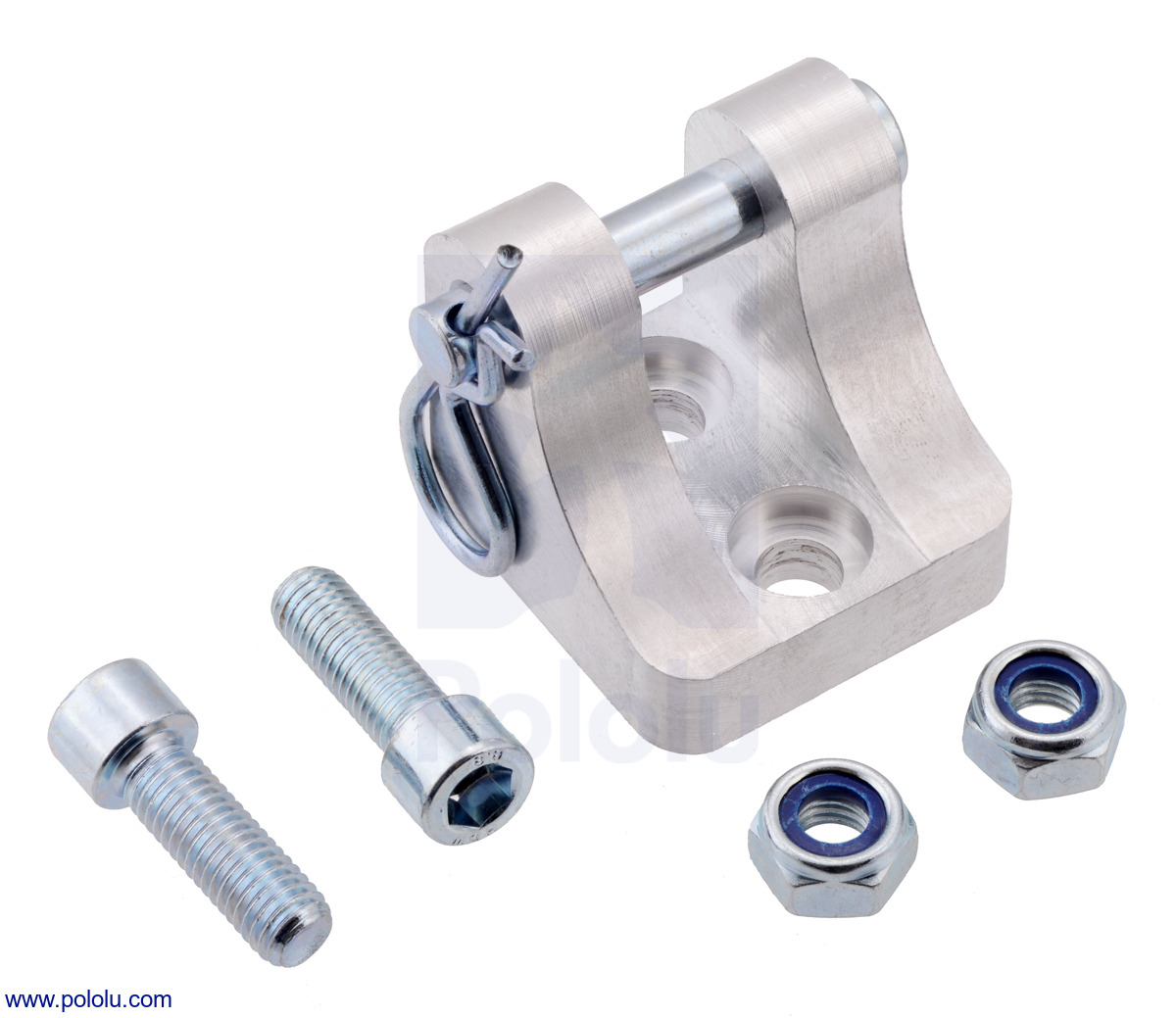
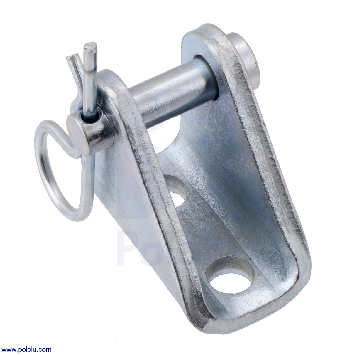
Mounting brackets made from machined aluminum or stamped steel are available for attaching the actuators to a structure; two are required for each actuator.
|
|
 |
Glideforce MD122006 Medium-Duty Linear Actuator: 100kgf, 6" Stroke, 0.58"/s, 12V. |
|---|
The following specifications apply to all Glideforce MD series linear actuators with the standard 20:1 gear ratio:
|
For more details, see the MD series datasheet (1MB pdf).
Diagrams of the linear actuators are shown below. The versions that include potentiometers have a larger gearbox, so their overall size and weight is larger. For more detailed information, including the retracted and extended lengths of each version, see the datasheet.
|
Dimensions of Glideforce MD linear actuators with feedback. Units are mm. |
|---|
|
Dimensions of Glideforce MD linear actuators without feedback. Units are mm. |
|---|
|
Glideforce MD122004 medium-duty linear actuator (4″ stroke) with shaft fully extended. |
|---|
To test-drive the actuator, simply connect a power source of up to 12 V to the motor leads. Reversing the applied voltage will reverse the direction of motion. A motor controller or motor driver is required for electronic speed and direction control. We recommend our Jrk G2 24v13 Motor Controllers for use with the feedback actuators (see below for more information on this) and the Simple Motor Controller G2 18v15 for controlling the actuators without feedback, though many of our other motor controllers and motor drivers are capable of powering this actuator.
These actuators have a stall current of 14 A at 12 V, but they will, on average, draw far less than this when used within their load ratings. They draw around 1 A with no load and can exceed 4 A at their maximum rated dynamic load. Note, however, that the actuators can briefly draw close to their full stall current when abruptly started or on a sudden change of direction. Such current spikes can be dampened if you take steps to limit the acceleration of the actuator (many of our motor controllers offer optional acceleration limiting).
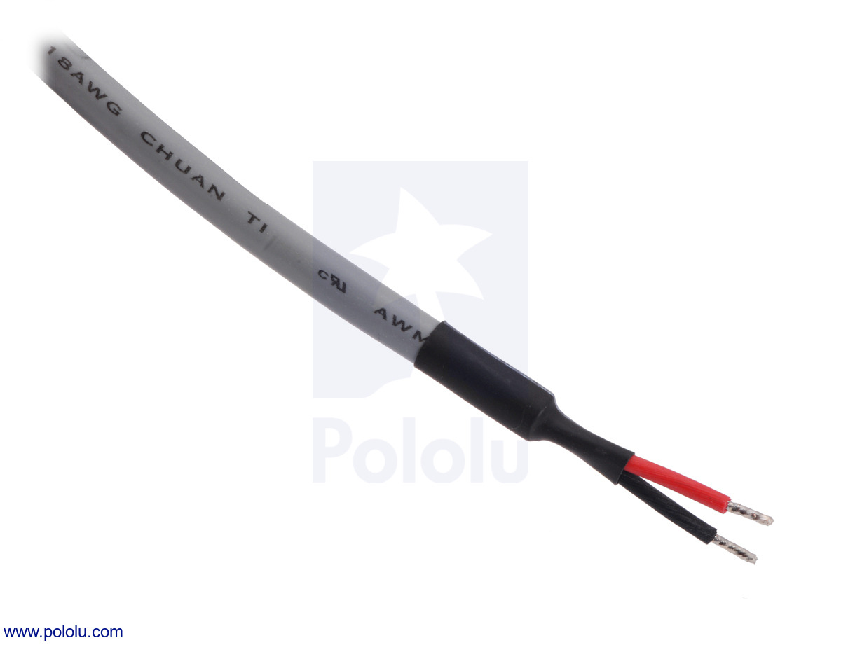
Actuators with feedback have a 26″ (90 cm) cable that is terminated with special female connectors as shown in the left picture below, one for the three potentiometer leads and another for the two power leads. These connectors match male versions on the extension cable for LD/MD linear actuators. Actuator versions without feedback have a 36″ (90 cm) cable with two unterminated, stripped power leads as shown in the right picture below. Linear actuators without feedback do not have cables that are compatible with the linear actuator extension cable.
|
|
|
Connecting a medium-duty linear actuator with feedback to a Jrk 24v13 motor controller. |
|---|
The feedback features of our Jrk G2 24v13 motor controller make it a great solution for precisely controlling our linear actuators with feedback. Our settings file for the Jrk G2 configuration utility makes setup easy, eliminating the need to tune the PID constants. To get started, follow the steps below:
 |
Glideforce linear actuators, from left to right: 6″ Industrial Duty (ID), 6″ Medium Duty (MD), 6″ Light Duty (LD), 50 mm Micro. |
|---|
We carry a variety of Glideforce linear actuators, from the Micro GF01 series, which weigh under 60 g, through the industrial-duty ID series, which can withstand dynamic loads up to 1000 lb. The table below shows our full offering of these linear actuators, sorted by increasing dynamic load capabilities:
| Actuator Type |
Max Dynamic Load |
No-Load Speed @ 12 V |
Max-Load Speed @ 12 V |
Current Draw @ 12 V |
Weight | Nominal Stroke Length |
With Feedback (no limit switches) |
With Limit Switches (no feedback) |
||
|---|---|---|---|---|---|---|---|---|---|---|
 |
Micro (GF01) 50:1 |
2.2 kgf [4.9 lb] |
2.8 cm/s [1.1″/s] |
2.1 cm/s [0.8″/s] |
0.15 A – 0.4 A |
31 g | 1 cm | (0.39″) | — | GF01-120501-1-66 |
| 37 g | 3 cm | (1.2″) | GF01-120503-2-66 | GF01-120503-1-66 | ||||||
| 42 g | 5 cm | (2.0″) | GF01-120505-2-66 | GF01-120505-1-66 | ||||||
| 57 g | 10 cm | (3.9″) | GF01-120510-2-66 | GF01-120510-1-66 | ||||||
| Micro (GF01) 100:1 |
4.3 kgf [9.4 lb] |
1.8 cm/s [0.7″/s] |
1.2 cm/s [0.5″/s] |
0.15 A – 0.3 A |
31 g | 1 cm | (0.39″) | — | GF01-121001-1-66 | |
| 39 g | 3 cm | (1.2″) | GF01-121003-2-66 | GF01-121003-1-66 | ||||||
| 44 g | 5 cm | (2.0″) | GF01-121005-2-66 | GF01-121005-1-66 | ||||||
| 59 g | 10 cm | (3.9″) | GF01-121010-2-66 | GF01-121010-1-66 | ||||||
| Micro (GF01) 210:1 |
8.1 kgf [18 lb] |
0.9 cm/s [0.3″/s] |
0.6 cm/s [0.2″/s] |
0.15 A – 0.25 A |
31 g | 1 cm | (0.39″) | — | GF01-122101-1-66 | |
| 39 g | 3 cm | (1.2″) | GF01-122103-2-66 | GF01-122103-1-66 | ||||||
| 44 g | 5 cm | (2.0″) | GF01-122105-2-66 | GF01-122105-1-66 | ||||||
| 59 g | 10 cm | (3.9″) | GF01-122110-2-66 | GF01-122110-1-66 | ||||||
| Actuator Type |
Max Dynamic Load |
No-Load Speed @ 12 V |
Max-Load Speed @ 12 V |
Current Draw @ 12 V |
Weight | Nominal Stroke Length |
With Feedback |
Without Feedback |
||
 |
High-Speed Light-Duty (LD) 5:1 |
12 kgf [27 lb] |
8.4 cm/s [3.3″/s] |
7.5 cm/s [2.9″/s] |
1.1 A – 3.4 A |
1.1 kg | 2″ | (5 cm) | GF23-120502-3-65 | GF23-120502-1-65 |
| 1.2 kg | 4″ | (10 cm) | GF23-120504-3-65 | GF23-120504-1-65 | ||||||
| 1.3 kg | 6″ | (15 cm) | GF23-120506-3-65 | GF23-120506-1-65 | ||||||
| 1.3 kg | 8″ | (20 cm) | GF23-120508-3-65 | GF23-120508-1-65 | ||||||
| 1.4 kg | 10″ | (25 cm) | GF23-120510-3-65 | GF23-120510-1-65 | ||||||
| 1.5 kg | 12″ | (30 cm) | GF23-120512-3-65 | GF23-120512-1-65 | ||||||
| Light-Duty (LD) 5:1 |
15 kgf [34 lb] |
4.4 cm/s [1.7″/s] |
3.6 cm/s [1.4″/s] |
1.2 A – 3.2 A |
1.1 kg | 2″ | (5 cm) | LACT2P-12V-05 | LACT2-12V-05 | |
| 1.2 kg | 4″ | (10 cm) | LACT4P-12V-05 | LACT4-12V-05 | ||||||
| 1.3 kg | 6″ | (15 cm) | LACT6P-12V-05 | LACT6-12V-05 | ||||||
| 1.3 kg | 8″ | (20 cm) | LACT8P-12V-05 | LACT8-12V-05 | ||||||
| 1.4 kg | 10″ | (25 cm) | LACT10P-12V-05 | LACT10-12V-05 | ||||||
| 1.5 kg | 12″ | (30 cm) | LACT12P-12V-05 | LACT12-12V-05 | ||||||
| Light-Duty (LD) 10:1 |
25 kgf [55 lb] |
2.8 cm/s [1.1″/s] |
2.3 cm/s [0.9″/s] |
1.2 A – 3.2 A |
1.1 kg | 2″ | (5 cm) | LACT2P-12V-10 | LACT2-12V-10 | |
| 1.2 kg | 4″ | (10 cm) | LACT4P-12V-10 | LACT4-12V-10 | ||||||
| 1.3 kg | 6″ | (15 cm) | LACT6P-12V-10 | LACT6-12V-10 | ||||||
| 1.3 kg | 8″ | (20 cm) | LACT8P-12V-10 | LACT8-12V-10 | ||||||
| 1.4 kg | 10″ | (25 cm) | LACT10P-12V-10 | LACT10-12V-10 | ||||||
| 1.5 kg | 12″ | (30 cm) | LACT12P-12V-10 | LACT12-12V-10 | ||||||
| Light-Duty (LD) 20:1 |
50 kgf [110 lb] |
1.5 cm/s [0.57″/s] |
1.2 cm/s [0.48″/s] |
1.2 A – 3.2 A |
1.1 kg | 2″ | (5 cm) | LACT2P-12V-20 | LACT2-12V-20 | |
| 1.2 kg | 4″ | (10 cm) | LACT4P-12V-20 | LACT4-12V-20 | ||||||
| 1.3 kg | 6″ | (15 cm) | LACT6P-12V-20 | LACT6-12V-20 | ||||||
| 1.3 kg | 8″ | (20 cm) | LACT8P-12V-20 | LACT8-12V-20 | ||||||
| 1.4 kg | 10″ | (25 cm) | LACT10P-12V-20 | LACT10-12V-20 | ||||||
| 1.5 kg | 12″ | (30 cm) | LACT12P-12V-20 | LACT12-12V-20 | ||||||
| Actuator Type |
Max Dynamic Load |
No-Load Speed @ 12 V |
Max-Load Speed @ 12 V |
Current Draw @ 12 V |
Weight | Nominal Stroke Length |
With Feedback |
Without Feedback |
||
 |
Medium-Duty (MD) |
100 kgf [225 lb] |
1.5 cm/s [0.58″/s] |
1.0 cm/s [0.41″/s] |
1.1 A – 4.6 A |
1.1 kg | 4″ | (10 cm) | MD122004-P | MD122004 |
| 1.2 kg | 6″ | (15 cm) | MD122006-P | MD122006 | ||||||
| 1.3 kg | 8″ | (20 cm) | MD122008-P | MD122008 | ||||||
| 1.4 kg | 10″ | (25 cm) | MD122010-P | MD122010 | ||||||
| 1.5 kg | 12″ | (30 cm) | MD122012-P | MD122012 | ||||||
| Actuator Type |
Max Dynamic Load |
No-Load Speed @ 12 V |
Max-Load Speed @ 12 V |
Current Draw @ 12 V |
Weight | Nominal Stroke Length |
With Feedback |
Without Feedback |
||
 |
Industrial-Duty (ID) with Acme screw drive |
250 kgf [550 lb] |
1.7 cm/s [0.66″/s] |
1.4 cm/s [0.56″/s] |
2.4 A – 13.2 A |
4.2 kg | 4″ | (10 cm) | LACT4-500APL | LACT4-500AL |
| 4.4 kg | 6″ | (15 cm) | LACT6-500APL | LACT6-500AL | ||||||
| 4.7 kg | 8″ | (20 cm) | LACT8-500APL | LACT8-500AL | ||||||
| 5.3 kg | 12″ | (30 cm) | LACT12-500APL | LACT12-500AL | ||||||
| 6.0 kg | 18″ | (45 cm) | LACT18-500APL | LACT18-500AL | ||||||
| 7.0 kg | 24″ | (60 cm) | LACT24-500APL | LACT24-500AL | ||||||
| Industrial-Duty (ID) with ball screw drive |
450 kgf [1000 lb] |
1.7 cm/s [0.66″/s] |
1.4 cm/s [0.56″/s] |
2.4 A – 13.2 A |
4.6 kg | 4″ | (10 cm) | LACT4-1000BPL | LACT4-1000BL | |
| 4.9 kg | 6″ | (15 cm) | LACT6-1000BPL | LACT6-1000BL | ||||||
| 5.1 kg | 8″ | (20 cm) | LACT8-1000BPL | LACT8-1000BL | ||||||
| 5.6 kg | 12″ | (30 cm) | LACT12-1000BPL | LACT12-1000BL | ||||||
| 6.5 kg | 18″ | (45 cm) | LACT18-1000BPL | LACT18-1000BL | ||||||
| 7.4 kg | 24″ | (60 cm) | LACT24-1000BPL | LACT24-1000BL | ||||||
| Nominal stroke length: | 6 in |
|---|---|
| Actual stroke length: | 5.91 in |
| Retracted length: | 10.04 in |
| Extended length: | 15.94 in |
| Weight: | 1.07 kg |
| Gear ratio: | 20:1 |
|---|---|
| Current @ 12V, no load: | 1.1 A |
| Current @ 12V, max load: | 4.6 A |
| Stall current @ 12V: | 14 A1 |
| Linear speed @ 12V, no load: | 0.58 in/s |
| Linear speed @ 12V, max load: | 0.41 in/s |
| Max linear force @ 12V: | 225 lb2 |
| Maximum duty cycle: | 25%3 |
| Feedback potentiometer included?: | N |
| Limit switches included?: | Y |
| Minimum operating temperature: | -25.0 °C |
| Maximum operating temperature: | 65 °C |
| IP rating: | IP654 |
This file contains 3D models (in the step file format) of the Glideforce medium-duty linear actuators with and without feedback.
Use a Jrk G2 24v13 to precisely control our Glideforce medium-duty (MD) series linear actuators with feedback. Instructions for using this file can be found on the linear actuator product pages.
No FAQs available.
No blog posts to show.