

This is a merged information page for Item #960.
View normal product page.
Pololu item #:
960
Brand:
Pololu
Status:
Active and Preferred

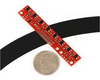
This sensor module has 8 IR LED/phototransistor pairs mounted on a 0.375" pitch, making it a great detector for a line-following robot. Pairs of LEDs are arranged in series to halve current consumption, and a MOSFET allows the LEDs to be turned off for additional sensing or power-savings options. Each sensor provides a separate analog voltage output.
 Compare all products in Older QTR Sensors.
 |
QTR-8A reflectance sensor array. |
|---|
 |
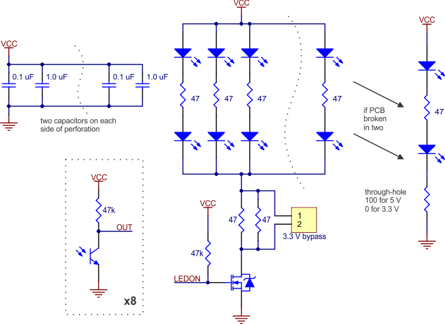
Schematic diagram of the QTR-8A reflectance sensor array. |
|---|
 |
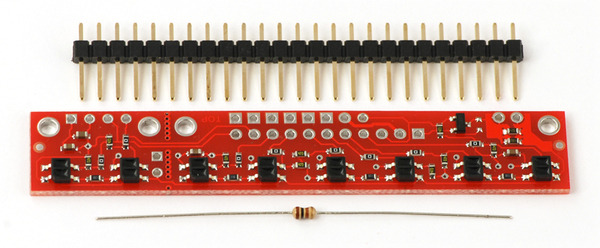
QTR-8A reflectance sensor array with included 25-pin 0.1" header strip and 100 Ohm through-hole resistor. |
|---|
 |
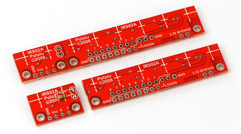
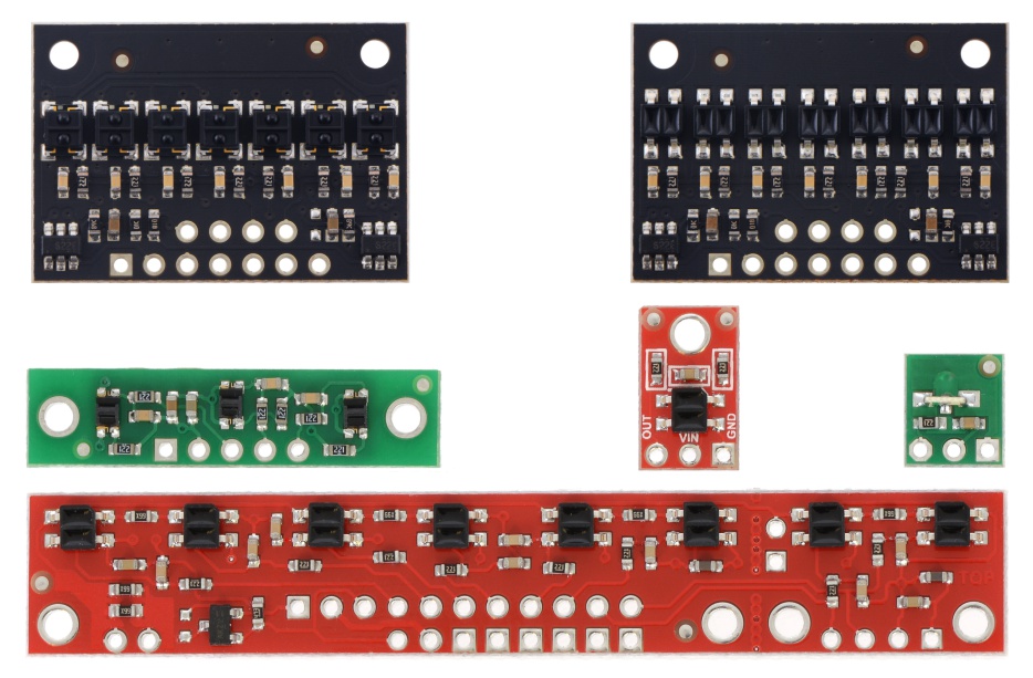
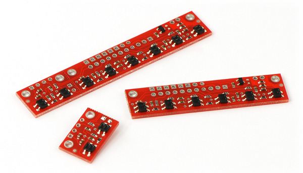
The QTR-8A reflectance sensor can separate into two smaller, functional arrays of length 2 and 6. |
|---|
 |
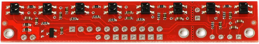
The bottom of the QTR-8A reflectance sensor array PCB, showing silkscreen labeling. |
|---|
 |
Solder the included resistor to the 2-sensor array piece as shown to make the separated piece functional. |
|---|
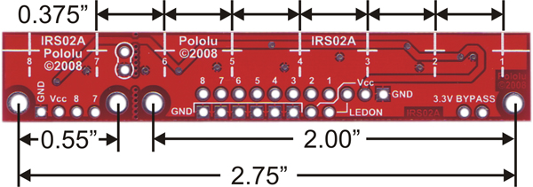 |
QTR-8A and QTR-8RC reflectance sensor array dimensions. |
|---|
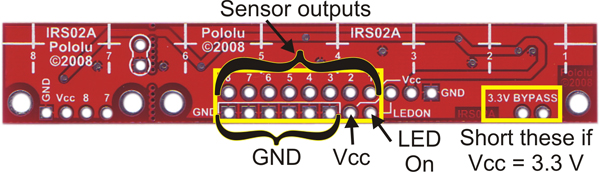 |
QTR-8x reflectance sensor array with 8×2 connection pins labeled. |
|---|
 |
QTR-8x reflectance sensor array with 11×1 connection pins labeled. |
|---|
 |
QTR-8A reflectance sensor array on a 3/4" line with a quarter for size reference. |
|---|
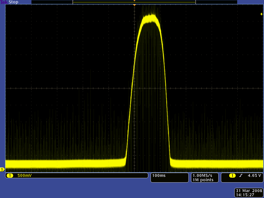 |
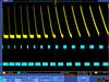
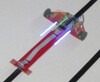
QTR-1A output 1/8" away from a spinning white disk with a black line on it. |
|---|
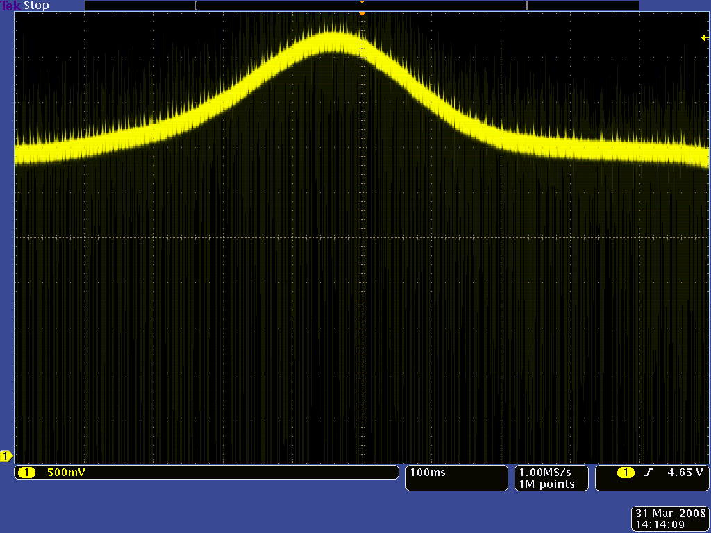 |
QTR-1A output 3/8" away from a spinning white disk with a black line on it. |
|---|
 |
QTR sensor size comparison. Top row: QTRX-HD-07, QTR-HD-07; middle row: QTR-3, QTR-1, QTR-L-1; bottom row: QTR-8. |
|---|
Note: The QTR-8A reflectance sensor array requires analog inputs to take readings. The similar QTR-8RC reflectance sensor array is available with digital I/O-compatible outputs, and the reflectance sensor is available individually as a QTR-1A reflectance sensor or QTR-1RC reflectance sensor.
|
The QTR-8A reflectance sensor array is intended as a line sensor, but it can be used as a general-purpose proximity or reflectance sensor. The module is a convenient carrier for eight IR emitter and receiver (phototransistor) pairs evenly spaced at intervals of 0.375" (9.525 mm). Each phototransistor is connected to a pull-up resistor to form a voltage divider that produces an analog voltage output between 0 V and VIN (which is typically 5 V) as a function of the reflected IR. Lower output voltage is an indication of greater reflection.
The outputs are all independent, but the LEDs are arranged in pairs to halve current consumption. The LEDs are controlled by a MOSFET with a gate normally pulled high, allowing the LEDs to be turned off by setting the MOSFET gate to a low voltage. Turning the LEDs off might be advantageous for limiting power consumption when the sensors are not in use or for varying the effective brightness of the LEDs through PWM control.
The LED current-limiting resistors for 5 V operation are arranged in two stages; this allows a simple bypass of one stage to enable operation at 3.3 V. The LED current is approximately 20-25 mA, making the total board consumption just under 100 mA. The schematic diagram of the module is shown below:
 |
For a similar array with three sensors, consider our QTR-3A reflectance sensor array. The sensors on the QTR-8A are also available individually as the QTR-1A reflectance sensor, and the QTR-L-1A is an alternative designed to be used with the board perpendicular to the surface.
|
QTR sensor size comparison. Top row: QTRX-HD-07, QTR-HD-07; middle row: QTR-3, QTR-1, QTR-L-1; bottom row: QTR-8. |
|---|
There are several ways you can interface with the QTR-8A outputs:
This last method will work if you are able to get high reflectance from your white surface as depicted in the left image, but will probably fail if you have a lower-reflectance signal profile like the one on the right.
|
|
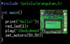
Our Pololu AVR library provides functions that make it easy to use these sensors with our Orangutan robot controllers; please see the QTR Reflectance Sensors section of our library command reference for more information. We also have a Arduino library for these sensors.
If you don’t need or cannot fit all eight sensors, you can break off two sensors and still use all 8 sensors as two separate modules, as shown below. The PCB can be scored from both sides along the perforation and then bent until it snaps apart. Each of the two resulting pieces will function as an independent line sensor.
 |
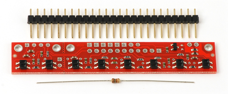
This module ships with a 25-pin 0.1" header strip and a 100 Ohm through-hole resistor as shown below.
 |
You can break the header strip into smaller pieces and solder them onto your reflectance sensor array as desired, or you can solder wires directly to the unit or use a right-angle header strip for a more compact installation. The pins on the module are arranged so that they can all be accessed using either an 11×1 strip or an 8×2 strip.
The resistor is required to make the two-sensor array functional after the original eight-sensor array is broken into two pieces. This resistor is only needed once the board has been broken.
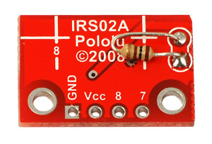 |
Solder the included resistor to the 2-sensor array piece as shown to make the separated piece functional. |
|---|
User’s guide for the QTR-8A reflectance sensor array.
Information about using the Pololu QTR reflectance sensors, including differences between A-type and RC-type sensors and sample oscilloscope screen captures of sensor outputs.
Information about installing and using the C/C++ libraries provided for use with Pololu products.

A reference to commands provided in the Pololu C/C++ and Arduino libraries for the AVR.
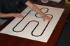
Step-by-step instructions for building your own line-following courses.
This is the sensor that we initially used in the Pololu QTR reflectance sensors, but we have since switched to a similar generic unit that has slightly longer range.
This DXF drawing shows the locations of all of the board’s holes.
Un guide utiliser et exploiter un senseur QTR (détecteur de ligne) (version 0.1). Note: This French translation of our QTR sensor documentation was made by our distributor MCHobby.
This library for Arduino makes it easy to interface with Pololu QTR Reflectance Sensors.
Matthew Phillipps ported our Arduino Library for the Pololu QTR Reflectance Sensors to the mbed platform. The Arduino library is designed to work with Pololu QTR reflectance sensors, so the mbed library should too, but Matthew points out he only tested it with the analog sensors. This library was not written and is not maintained by Pololu.
No FAQs available.
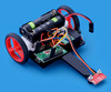
Two Point Four was my entry in the LVBots 2015 line following competition, originally built for our 2013 contest but significantly rebuilt since...
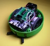
Abe Howell posted to our forum about a Kickstarter campaign for a robot he calls Apeiros. It is an open-source robot he designed as a teaching tool...
This excellent guide from C.I.r.E. (Club de Informática, robótica y Electrónica) shows in detail how to build a fast (> 2 m/s) line-following...