

This is a merged information page for Item #1353.
View normal product page.
Pololu item #:
1353
Brand:
Pololu
Status:
Active and Preferred

The 12-channel Mini Maestro 12 raises the performance bar for serial servo controllers with features such as a native USB interface and internal scripting control. Whether you want the best servo control available (0.25μs resolution with built-in speed and acceleration control and pulse rates up to 333 Hz) or a general I/O controller (e.g. to interface with a sensor or ESC via your USB port), this compact, versatile device will deliver. Header pins are included but not soldered into this partial kit version (all surface-mount components are soldered).
Alternatives available with variations in these parameter(s): channels partial kit? Select variant…
 Compare all products in Maestro USB Servo Controllers or RC Servo Controllers or Computer Interface.
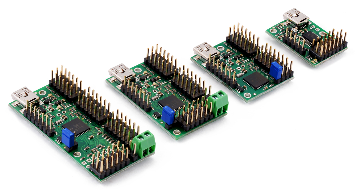 |
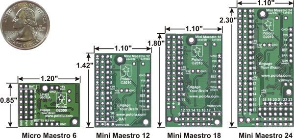
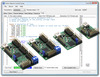
Maestro family of USB servo controllers: Mini 24, Mini 18, Mini 12, and Micro 6. |
|---|
 |
Bottom view with dimensions (in inches) of Pololu Micro and Mini Maestro servo controllers. |
|---|
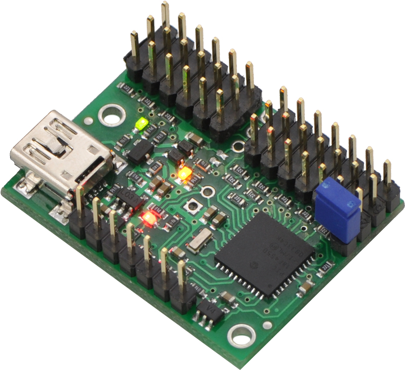 |
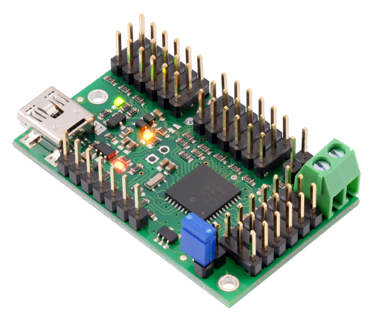
Mini Maestro 12-channel USB servo controller (assembled version). |
|---|
|
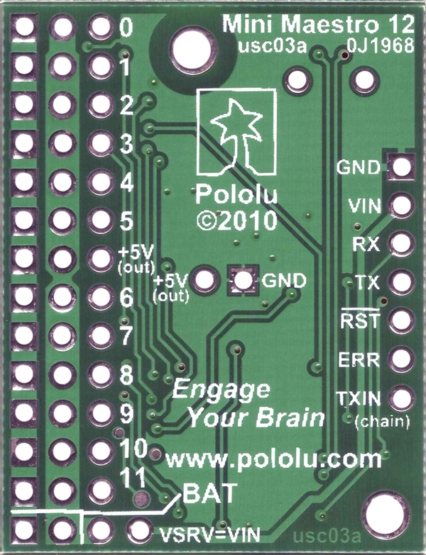
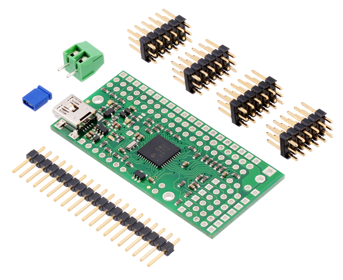
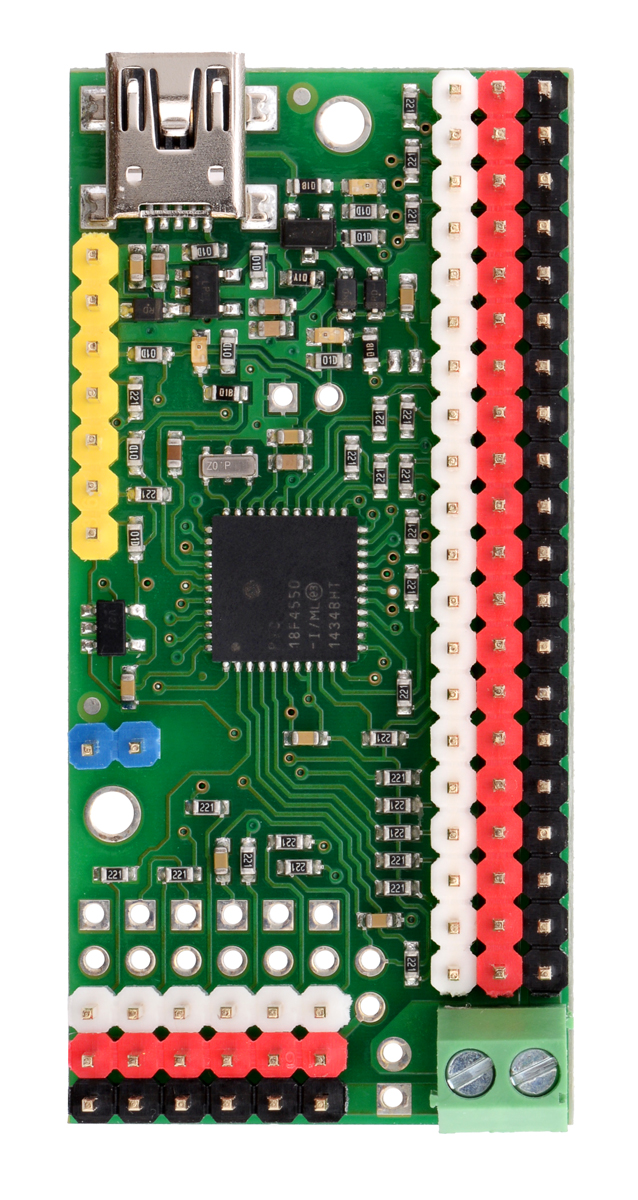
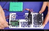
Mini Maestro 12-channel USB servo controller (partial kit version). |
|---|
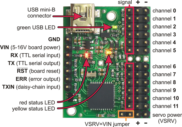 |
Mini Maestro 12-channel USB servo controller (fully assembled) labeled top view. |
|---|
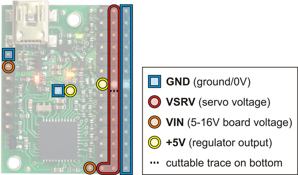 |
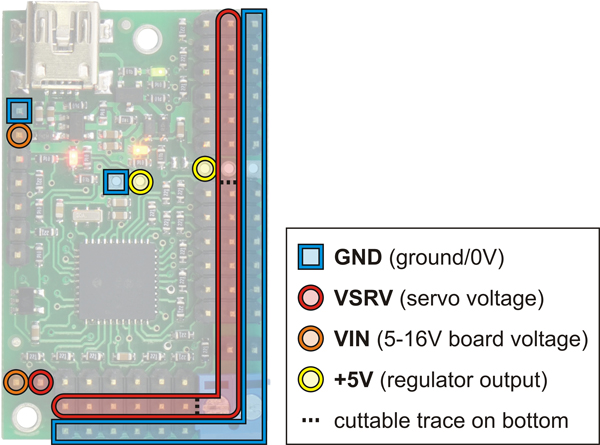
Mini Maestro 12 power pins. |
|---|
 |
Bottom view of Mini Maestro 12-channel USB servo controller. |
|---|
 |
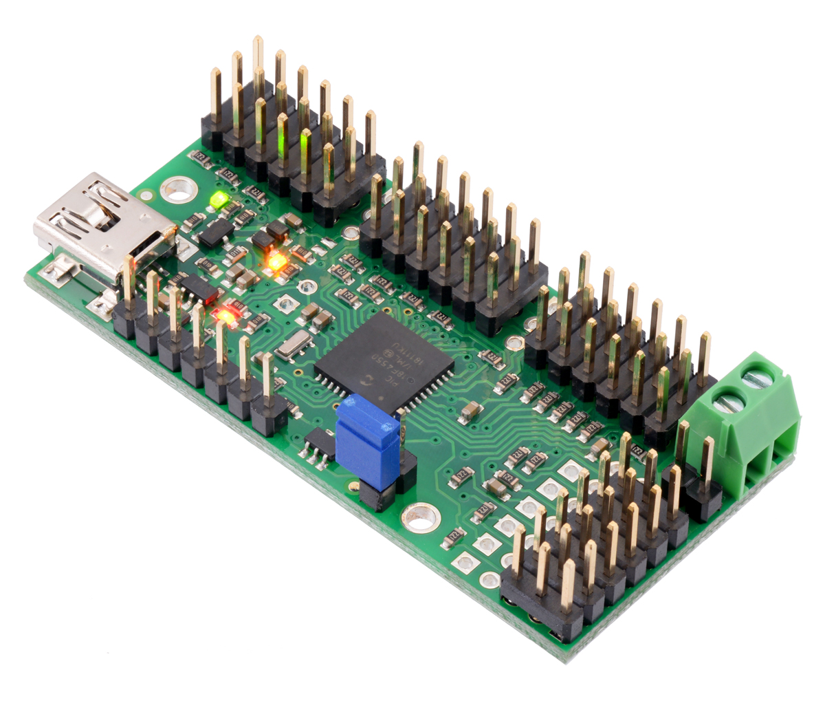
Mini Maestro 18-channel USB servo controller (assembled version). |
|---|
 |
Mini Maestro 18-channel USB servo controller (partial kit version). |
|---|
 |
Mini Maestro 18-channel USB servo controller (fully assembled) labeled top view. |
|---|
 |
Mini Maestro 18 power pins. |
|---|
 |
Bottom view of Mini Maestro 18-channel USB servo controller. |
|---|
 |
Mini Maestro 24-channel USB servo controller (assembled version). |
|---|
 |
Mini Maestro 24-channel USB servo controller (partial kit version). |
|---|
 |
Mini Maestro 24-channel USB servo controller (fully assembled) labeled top view. |
|---|
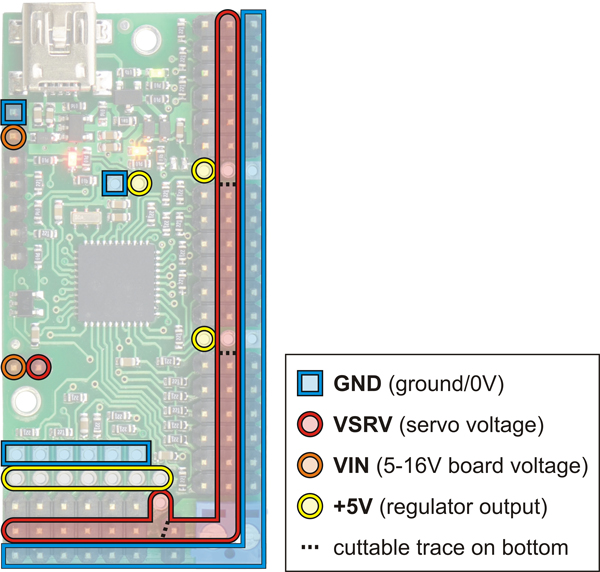 |
Mini Maestro 24 power pins. |
|---|
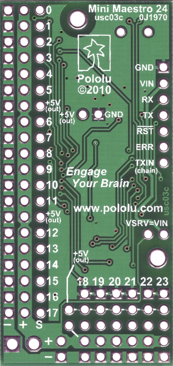 |
Bottom view of Mini Maestro 24-channel USB servo controller. |
|---|
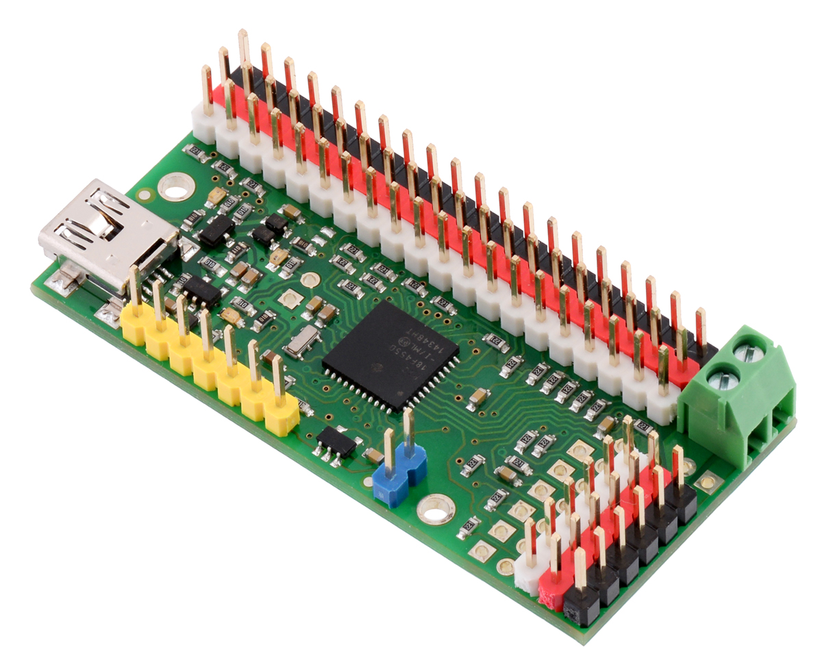 |
24-channel Mini Maestro (partial kit version) assembled with colored male header pins. |
|---|
 |
24-channel Mini Maestro (partial kit version) assembled with colored male header pins. |
|---|
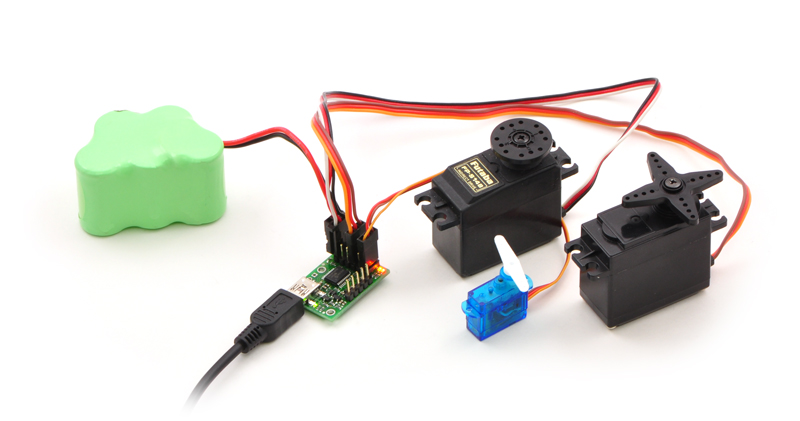 |
Micro Maestro 6-channel USB servo controller (fully assembled) controlling three servos. |
|---|
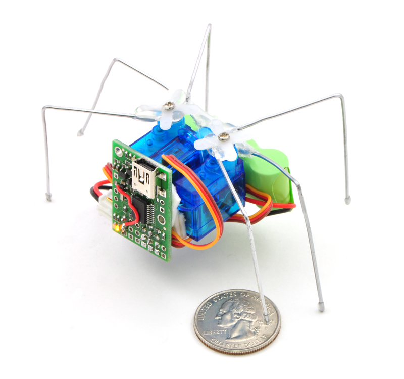 |
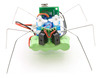
Micro Maestro as the brains of a tiny hexapod robot. |
|---|
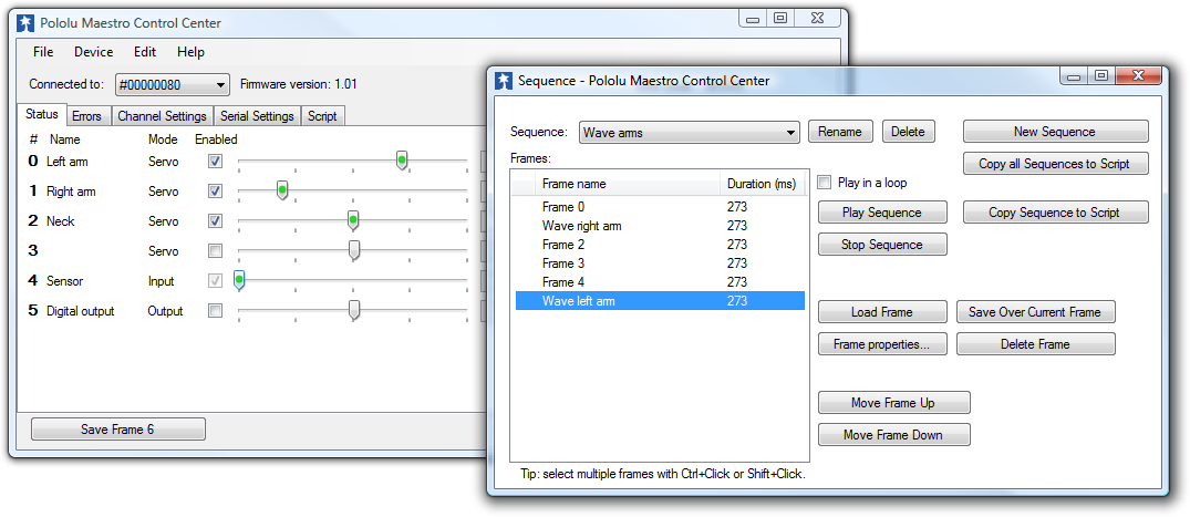 |
Creating a sequence of servo movements using the Maestro Control Center. |
|---|
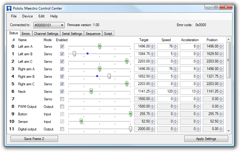 |
The Status tab in the Maestro Control Center. |
|---|
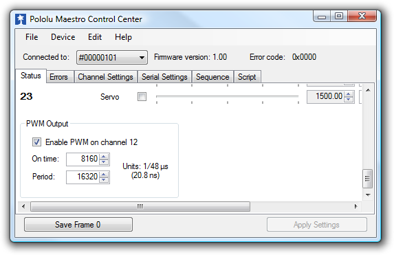 |
The PWM Output control in the Status tab in the Maestro Control Center (only available on the Mini Maestro 12, 18, and 24). |
|---|
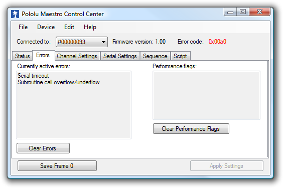 |
The Errors tab in the Maestro Control Center. |
|---|
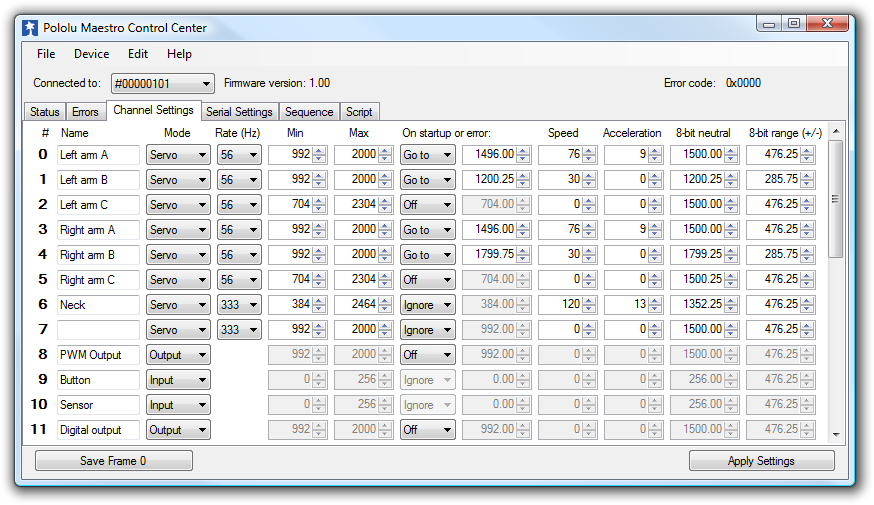 |
The Channel Settings tab in the Maestro Control Center. |
|---|
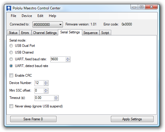 |
The Serial Settings tab in the Maestro Control Center. |
|---|
 |
The Sequence tab in the Maestro Control Center. |
|---|
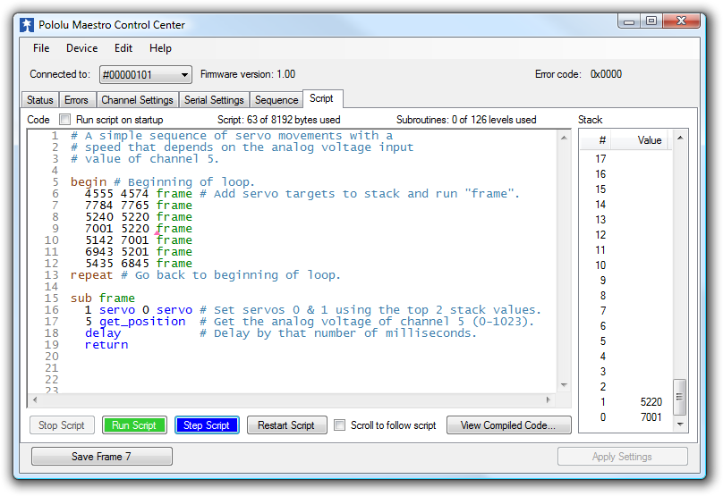 |
The Script tab in the Maestro Control Center. |
|---|
For a full list of products shown in this video, see the blog post.
|
Maestro family of USB servo controllers: Mini 24, Mini 18, Mini 12, and Micro 6. |
|---|
The Mini Maestros are the newest of Pololu’s second-generation USB servo controllers, offering more channels and features than the smaller six-channel Micro Maestro. The Mini Maestros are available in three sizes, and they can be purchased fully assembled or as partial kits:
The Mini Maestros are highly versatile (and compact) servo controllers and general-purpose I/O boards. They support three control methods: USB for direct connection to a computer, TTL serial for use with embedded systems, and internal scripting for self-contained, host controller-free applications. The channels can be configured as servo outputs for use with radio control (RC) servos or electronic speed controls (ESCs), as digital outputs, or as analog/digital inputs. The extremely precise, high-resolution servo pulses have a jitter of less than 200 ns, making these servo controllers well suited for high-performance applications such as robotics and animatronics, and built-in speed and acceleration control for each channel make it easy to achieve smooth, seamless movements without requiring the control source to constantly compute and stream intermediate position updates to the Mini Maestros. The Mini Maestros also feature configurable pulse rates from 1 to 333 Hz and can generate a wide range of pulses, allowing maximum responsiveness and range from modern servos. Units can be daisy-chained with additional Pololu servo and motor controllers on a single serial line.
|
The Status tab in the Maestro Control Center. |
|---|
A free configuration and control program is available for Windows and Linux, making it simple to configure and test the device over USB, create sequences of servo movements for animatronics or walking robots, and write, step through, and run scripts stored in the servo controller. The Mini Maestros’ 8 KB of internal script memory allows storage of up to approximately 3000 servo positions that can be automatically played back without any computer or external microcontroller connected.
Because the Mini Maestros’ channels can also be used as general-purpose digital outputs and analog or digital inputs, they provide an easy way to read sensors and control peripherals directly from a PC over USB, and these channels can be used with the scripting system to enable creation of self-contained animatronic displays that respond to external stimuli and trigger additional events beyond just moving servos.
 |
The fully assembled versions of the Mini Maestro ship with 0.1″ male header pins installed as shown in the respective product pictures. The partial kit versions ship with these header pins included but unsoldered, which allows the use of different gender connectors or wires to be soldered directly to the pads for lighter, more compact installations. A USB A to mini-B cable (not included) is required to connect this device to a computer. The Micro and Mini Maestros have 0.086″ diameter mounting holes that work with #2 and M2 screws.
|
Micro Maestro 6-channel USB servo controller (fully assembled) controlling three servos. |
|---|
|
The Channel Settings tab in the Maestro Control Center. |
|---|
 |
 |
 |
 |
||||||||
|---|---|---|---|---|---|---|---|---|---|---|---|
| Micro Maestro | Mini Maestro 12 | Mini Maestro 18 | Mini Maestro 24 | ||||||||
| Channels: | 6 | 12 | 18 | 24 | |||||||
| Analog input channels: | 6 | 12 | 12 | 12 | |||||||
| Digital input channels: | 0 | 0 | 6 | 12 | |||||||
| Width: | 0.85" (2.16 cm) | 1.10" (2.79 cm) | 1.10" (2.79 cm) | 1.10" (2.79 cm) | |||||||
| Length: | 1.20" (3.05 cm) | 1.42" (3.61 cm) | 1.80" (4.57 cm) | 2.30" (5.84 cm) | |||||||
| Weight(1): | 3.0 g | 4.2 g | 4.9 g | 6.0 g | |||||||
| Configurable pulse rate(2): | 33 Hz to 100 Hz | 1 Hz to 333 Hz | 1 Hz to 333 Hz | 1 Hz to 333 Hz | |||||||
| Pulse range(2): | 64 μs to 3280 μs | 64 μs to 4080 μs | 64 μs to 4080 μs | 64 μs to 4080 μs | |||||||
| Script size(3): | 1 KB | 8 KB | 8 KB | 8 KB | |||||||
| Price: | $27.95 | $37.95 | $46.95 | $54.95 | |||||||
| 1 This is the weight of the board without header pins or terminal blocks. 2 The available pulse rate and range depend on each other and factors such as baud rate and number of channels used. 3 The user script system is more powerful on the Mini Maestro than on the Micro Maestro. |
|||||||||||
The Micro and Mini Maestros are available with through-hole connectors preinstalled or as partial kits, with the through-hole connectors included but not soldered in. The preassembled versions are appropriate for those who want to be able to use the product without having to solder anything or who are happy with the default connector configuration, while the partial kit versions enable the installation of custom connectors, such as right-angle headers that allow servos to be plugged in from the side rather than the top, or colored header pins that make it easier to tell which way to plug in the servo cables. The following picture shows an example of a partial-kit version of the 24-channel Mini Maestro assembled with colored male header pins:
|
24-channel Mini Maestro (partial kit version) assembled with colored male header pins. |
|---|
|
Micro Maestro as the brains of a tiny hexapod robot. |
|---|
An example setup using a Micro Maestro to control a ShiftBar and Satellite LED Module is shown in the picture below and one of the videos above. Maestro source code to control a ShiftBar or ShiftBrite is available in the Example scripts section of the Maestro User’s guide.
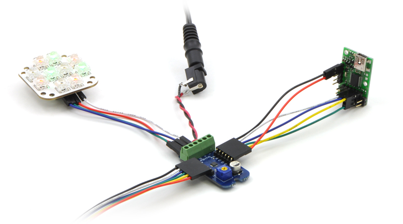 |
Connecting the Micro Maestro to a chain of ShiftBars. A single 12V supply powers all of the devices. |
|---|
| Size: | 1.10" x 1.42" |
|---|---|
| Weight: | 4.2 g1 |
| Channels: | 12 |
|---|---|
| Baud: | 300 - 200000 bps2 |
| Minimum operating voltage: | 5 V |
| Maximum operating voltage: | 16 V |
| Supply current: | 40 mA3 |
| Partial kit?: | Y |
| PCB dev codes: | usc03a |
|---|---|
| Other PCB markings: | 0J1968 |
User’s guide for the Pololu Micro Maestro 6-channel USB Servo Controller and the Pololu Mini Maestro 12-, 18-, and 24-Channel USB Servo Controllers.
The Pololu USB SDK contains example code for making your own applications that use native USB to control the Jrk Motor Controller, Maestro Servo Controller, Simple Motor Controller, or USB AVR Programmer.
This is a step-by-step tutorial showing you how to use the Pololu Micro Maestro to build a simple six-legged walking robot. The total parts cost is about $72.
An application note about using AutoHotkey for Windows to control Pololu USB products.
This ZIP archive contains the installation files for the Maestro Control Center, the Maestro command-line utility (UscCmd), and the Maestro drivers for Microsoft Windows.
This tar/gzip archive contains the binary executable files for the Maestro Control Center and the Maestro command-line utility (UscCmd) for Linux.
A Spanish version of the user’s guide for the Pololu Micro Maestro 6-channel USB Servo Controller and the Pololu Mini Maestro 12-, 18-, and 24-Channel USB Servo Controllers, provided by customer Jaume B.
This DXF drawing shows the locations of all of the board’s holes.
This DXF drawing shows the locations of all of the board’s holes.
This DXF drawing shows the locations of all of the board’s holes.
This program estimates how long the Maestro will take to perform a servo movement based on the configured speed and acceleration limits for the servo. It is packaged as an HTML file that you can run by downloading and then opening in any modern web browser.
In this short video, Pololu engineer Emily shows how easy it is to get started with Maestro servo controllers.
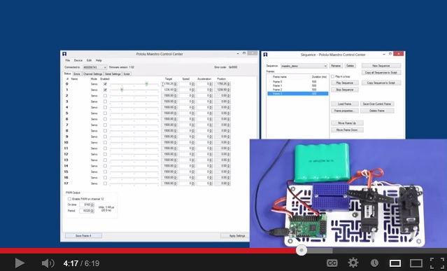 |
Getting started with the maestro servo controller. |
|---|
This library allows you to control Maestro Servo Controllers from an Arduino.
Polstro is a cross-platform C++ library for controlling a Maestro over its serial interface. Jacques Bitoniau created this library for his quadcopter control system, which is described in this blog post.
The Pololu Maestro RoboRealm module provides a way to interface the visual processing of RoboRealm into servo movements using the Pololu Maestro USB Servo Controller. Released February, 2010.
A simple obstacle-avoiding robot based on the Maestro, using continuous-rotation servos and distance sensors. The robot is programmed using the Maestro’s internal scripting language, without the need for an additional microcontroller. By TomatoWire, June 2010.
This Japanese-style lamp was made from laser-cut parts and uses an RGB LED Satellite Module 001, a ShiftBar, and a Pololu Mini Maestro 12-channel servo controller. By Kevin Chang, April 2013.
3D models of cases that cover the bottom of the 6-channel Micro Maestro and 12-channel Mini Maestro servo controllers.
Demo code to do web-based real time control of the Pololu Micro Maestro 6 channel servo controller using the Raspberry Pi and the Tornado web server. By MartinSant, November 2012.
The Microsoft .NET Framework version 3.5 is required for many Pololu configuration, control, and utility programs under Windows. Most computers will have this installed already or can automatically install it over the internet, but you can also get .NET 3.5 directly from Microsoft at this link. If you are installing on a computer without internet access, make sure to get the Full Redistributable Package.
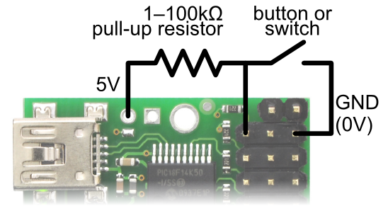 |
Diagram for connecting a button or switch to the Micro Maestro Servo Controller. |
|---|
First, decide which channel you would like to connect your button or switch to. In the Maestro Control Center, under the Channel Settings tab, change that channel to Input mode and click “Apply Settings”. Next, wire a pull-up resistor (1–100 kilo-ohms) between the signal line of that channel and 5 V so that the input is high (5 V) when the switch is open. Wire the button or switch between the signal line and GND (0 V) so that when the button/switch is active the input will fall to 0 V. The picture to the right shows how to connect a button or switch to channel 0.
You can test your input by toggling the button/switch and verifying that the “Position” variable as shown in the Status tab of the Maestro Control Center reflects the state of your button/switch: it should be close to 255.75 when the button/switch is active and close to 0 when it is inactive. Now you can read the state of the button/switch in your script using the GET_POSITION command or over serial using the “Get Position” command. These commands will return values that are close to 1023 when the button/switch is active and close to 0 when it is inactive. Warning: The Maestro’s I/O lines can only tolerate voltages from 0 to 5 V, so if your power supply is more than 5 V be careful not to connect it to the signal line.
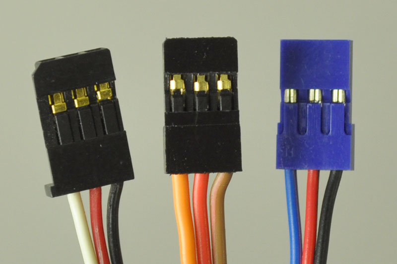 |
Most standard radio control (RC) servos have three wires, each a different color. Usually, they are either black, red, and white, or they are brown, red, and orange/yellow:
Please check the specs for your servo to determine the proper power supply voltage, and please take care to plug the servo into your device in the proper orientation (plugging it in backwards could break the servo or your device).
Note: Some of the servos we carry also have an optional fourth green wire that is separate from the three standard ones. This wire provides access to the feedback potentiometer, allowing you to directly measure the position of the output. The servos with this extra wire have "with Position Feedback" at the ends of their product names. The picture below is an example of such a servo.
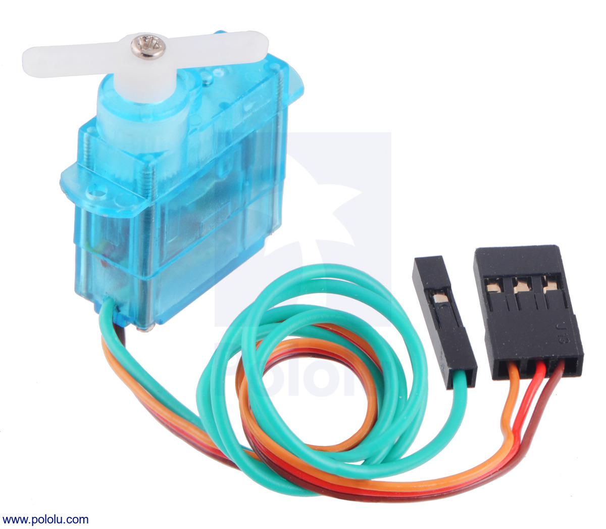 |
FEETECH Sub-Micro Servo FS0403-FB with Position Feedback. |
|---|
Be careful when going past the normal 90-degree range to avoid damaging your servo.
To find the settings in the Maestro Control Center that make your servo rotate as much as it can, first set the Min and Max values on the Channel Settings tab to a wider range. Then use the lowest possible supply voltage at which your servo moves and gradually move the slider on the status tab until the servo does not move any further or you hear the servo straining. Once you reach the limit, immediately move back from it to avoid damaging the servo. Finally, return to the channel settings tab and configure Min and Max so that the servo will never go past the limit.
When the Maestro first starts up, the servos could be in any position, and the Maestro has no way of determining what position they are in. The standard RC servo protocol provides no way to get feedback from a servo. Therefore, when the Maestro receives its first Set Target command for a servo, whether it comes from serial, USB or an internal script, it will not be able to produce a smooth transition from the current position to the target position and will instead command the servo to immediately go to the target position. The speed and acceleration limits will work for subsequent commands since the Maestro will know where the servo should be and can produce servo pulses that smoothly change from the current position to the target position.
If you need your servo’s first movement to be controlled by the speed and acceleration limits, then the first Set Target command you send to the Maestro should correspond to the servo’s current position. For example, if you know that your servo will always be at a position of 1500 μs when your system starts up, then your first Set Target command for that servo should have a value of 1500 μs.
Similarly, if you set the target of a servo to zero to make the Maestro stop sending pulses, the Maestro will lose its knowledge of where the servo is. During this time, the servo might slip and go to a different position. If you know your servo is not going to slip, then your program or internal script could remember where the servo is and send a Set Target command with that position in it before trying to move the servo to another position.
Make your next project more colorful with our new red, white, blue, and yellow breakaway male header strips. You can use them to add some personal...
We are excited to release this new video for our Maestro Servo Controllers! Get some ideas for cool things you can do with the Maestro, and see...
Two ShiftBrites controlled by Mini Maestros power a flashlight capable of displaying one million colors with many interesting modes of operation....