

This is a merged information page for Item #3759.
View normal product page.
Pololu item #:
3759
Brand:
Pololu
Status:
Active

This compact expansion board plugs directly into the GPIO header on a Raspberry Pi and provides an easy and low-cost solution for driving a pair of small brushed DC motors. Its pair of integrated MAX14870 motor drivers allows it to operate from 4.5 V to 36 V, making it a great control option for small motors that run on a wide range of voltages. The board can deliver a continuous 1.7 A (2.5 A peak) per motor. This version ships fully assembled with connectors soldered in.
Alternatives available with variations in these parameter(s): partial kit? Select variant…
 Compare all products in Raspberry Pi Expansion Boards or Brushed DC Motor Drivers.
|
Dual MAX14870 Motor Driver for Raspberry Pi (assembled), bottom view. |
|---|
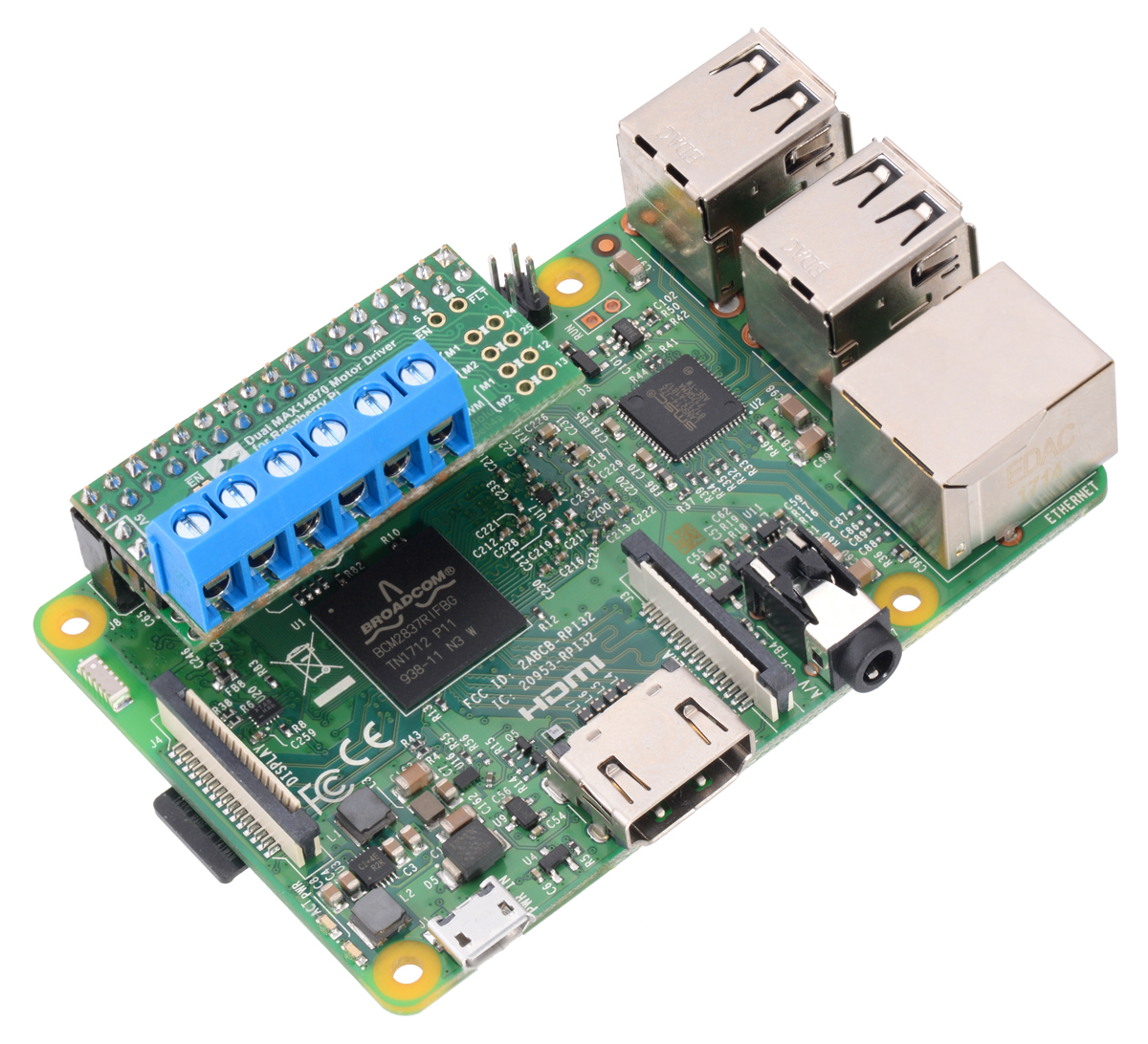 |
Dual MAX14870 Motor Driver for Raspberry Pi (assembled) on a Raspberry Pi 3 Model B. |
|---|
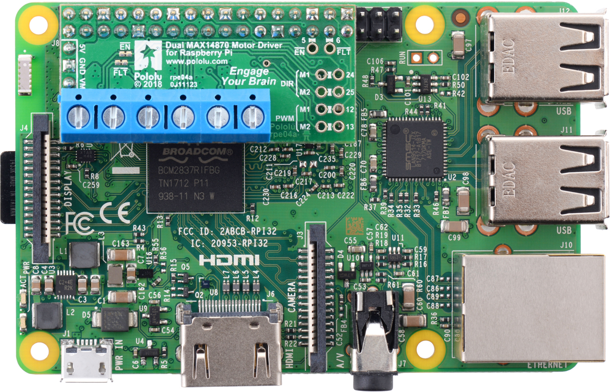 |
Dual MAX14870 Motor Driver for Raspberry Pi (assembled) on a Raspberry Pi 3 Model B. |
|---|
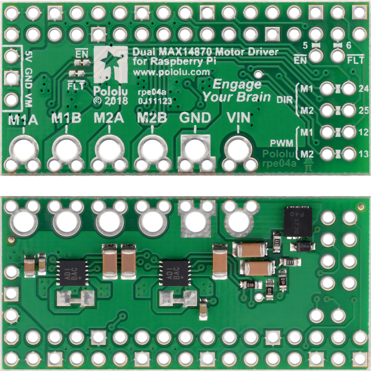 |
Dual MAX14870 Motor Driver for Raspberry Pi, top and bottom sides. |
|---|
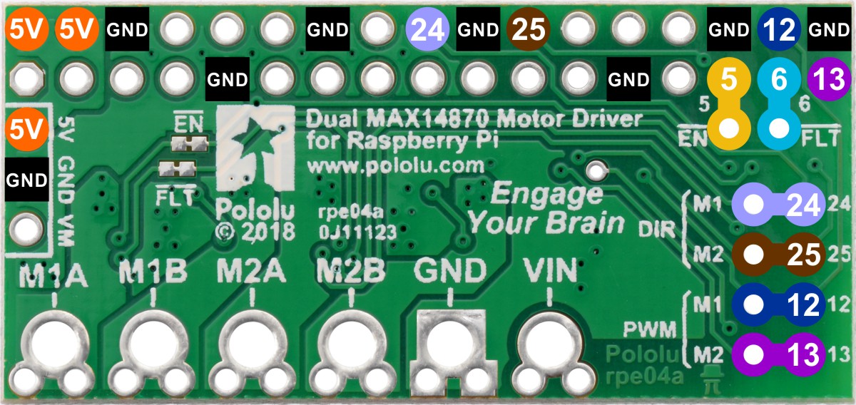 |
Pinout and default pin mappings of the Dual MAX14870 Motor Driver for Raspberry Pi. |
|---|
 |
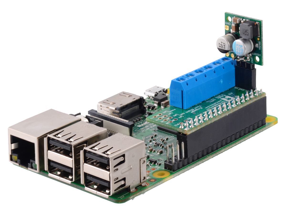
D24V10F5 5V 1A step-down voltage regulator soldered directly to Dual MAX14870 Motor Driver for Raspberry Pi (compact, permanent connection). |
|---|
 |
D24V10F5 5V 1A step-down voltage regulator soldered directly to Dual MAX14870 Motor Driver for Raspberry Pi (compact, permanent connection). |
|---|
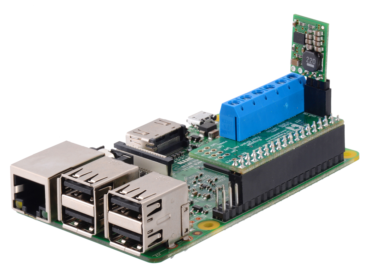 |
D24V10F5 5V 1A step-down voltage regulator plugged into a Dual MAX14870 Motor Driver for Raspberry Pi (temporary connection). |
|---|
 |
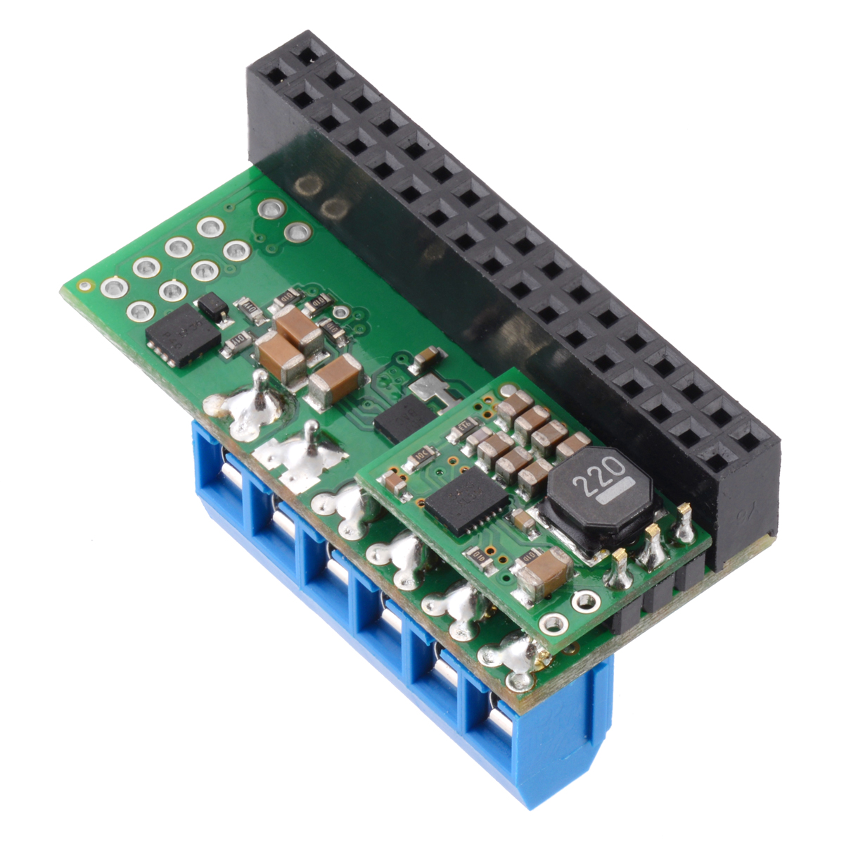
D24V22F5 5V 2.5A step-down voltage regulator plugged into a Dual MAX14870 Motor Driver for Raspberry Pi (temporary connection). |
|---|
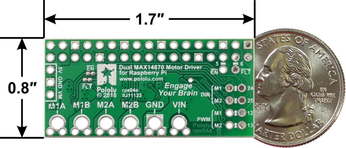 |
Dual MAX14870 Motor Driver for Raspberry Pi, top view with dimensions. |
|---|
This motor driver expansion board and its corresponding Python library make it easy to control a pair of bidirectional, brushed DC motors with a compatible Raspberry Pi (Model B+ or newer), including the Pi 3 Model B+ and Model A+. The expansion board features two MAX14870 H-bridge motor driver ICs from Maxim, which allow it to operate from 4.5 V to 36 V and make it well suited for driving small motors across a wide range of voltages. The board can deliver a continuous 1.7 A per channel and tolerate peak currents up to 2.5 A per channel for a few seconds. It is available either as a partial kit, with a female header and terminal blocks included but not soldered in, or fully assembled with these connectors soldered to the PCB.
The board’s default configuration uses five GPIO pins to control the motor drivers, making use of the Raspberry Pi’s hardware PWM outputs, and it uses one additional pin to read a fault output from the drivers. However, the pin mappings can be customized if the defaults are not convenient.
|
Note that this motor driver add-on is designed specifically for newer versions of the Raspberry Pi with 40-pin GPIO headers; it is not practical to use this expansion board with the original Raspberry Pi Model A or Model B due to differences in their pinout and form factor.
For controlling higher-power motors with a Raspberry Pi, consider our dual MC33926 motor driver add-on, and for lower-voltage motors, consider our DRV8835 dual motor driver kit. We also have a similar dual MAX14870 shield for Arduinos and Arduino-compatible boards and a single MAX14870 carrier for those with tighter space constraints or who only want to control one motor.
|
Dual MAX14870 Motor Driver for Raspberry Pi, top and bottom sides. |
|---|
This version of the motor driver is fully assembled, with a 2×17-pin 0.1″ female header (for connecting to the Raspberry Pi’s 40-pin GPIO header) and a six-pin strip of 5 mm terminal blocks (for motor and power connections) soldered in. (See item #3758 for a kit version with connectors included but not soldered in.)
|
Dual MAX14870 Motor Driver for Raspberry Pi (assembled), bottom view. |
|---|
A Raspberry Pi is not included.
This section explains how to use the dual MAX14870 motor driver add-on board and provides some basic information about the motor driver pins to help get you started. However, we strongly encourage you to consult the MAX14870 datasheet (492k pdf) for detailed pin descriptions, truth tables, and electrical characteristics. This expansion board is essentially a breakout board for two MAX14870 motor driver ICs, so the datasheet is your best resource for answering questions not covered here.
The board should be plugged into the leftmost position on the Raspberry Pi’s 40-pin GPIO header, leaving six pins exposed on the right, as shown in the picture below.
|
In the board’s default state, the motor driver and Raspberry Pi are powered separately, though they share a common ground. When used this way, the Raspberry Pi must be powered via its USB Micro-B receptacle, and the motor driver board must be supplied with 4.5 V to 36 V through its large VIN and GND pads. However, the motor driver board provides a set of three through-holes where you can conveniently connect an appropriate voltage regulator, allowing the motor supply to also power the Raspberry Pi (see the Powering the Raspberry Pi from the motor driver board section below).
This table shows how the Raspberry Pi’s GPIO pins are used to interface with the motor drivers:
| RPi GPIO pin |
Motor driver pin | Description |
|---|---|---|
| 5 | EN | Inverted enable input: The Raspberry Pi pulls this pin high by default, putting the motor driver IC into a low-current sleep mode and disabling the motor outputs (setting them to high impedance). EN must be driven low to enable the motor driver. |
| 6 | FAULT | Fault output: When the drivers are functioning normally, this pin should be pulled high by the Raspberry Pi. In the event of an over-current or over-temperature condition, the driver IC experiencing the fault drives FAULT low. |
| 12 | Motor 1 PWM | Motor speed input: A PWM (pulse-width modulation) signal on this pin corresponds to a PWM output on the corresponding driver’s motor outputs. When this pin is low, the motor brakes low. When it is high, the motor is on. The maximum allowed PWM frequency is 50 kHz. |
| 13 | Motor 2 PWM | |
| 24 | Motor 1 DIR | Motor direction input: When DIR is low, motor current flows from output A to output B; when DIR is high, current flows from B to A. |
| 25 | Motor 2 DIR |
This table shows how the drivers’ control inputs affect the motor outputs:
| Inputs | Outputs | ||||
|---|---|---|---|---|---|
| EN | DIR | PWM | MxA | MxB | operating mode |
| 0 | 0 | PWM | PWM (H/L) | L | forward/brake at speed PWM % |
| 0 | 1 | PWM | L | PWM (H/L) | reverse/brake at speed PWM % |
| 0 | X | 0 | L | L | brake low (outputs shorted to ground) |
| 1 | X | X | Z | Z | coast (outputs off) |
Each GPIO pin used by the board is connected to the corresponding motor driver pin by a trace on the top side of the board spanning a pair of holes. If you want to remap one of these motor driver pins, you can cut its trace with a knife and then run a wire from the lower hole to a new GPIO pin.
|
In addition, the EN and FAULT pins are connected between the two driver ICs by default. If you need to access each driver’s pins separately, you can cut the traces between the surface-mount jumpers labeled “EN” and “FAULT” next to the Pololu logo on the board. This leaves the right side of the jumpers and the original access points on the board connected to the EN and FAULT pins for motor 2, while the left side of the jumpers will provide access to those pins for motor 1.
Note that the default pin mappings were chosen so that the Raspberry Pi’s default GPIO pull-ups and pull-downs match the direction the motor driver pins are or should be pulled (up for EN and FAULT, down for others); if you remap the motor driver pins without paying attention to this, you might encounter issues with pins being pulled the wrong way. See the Raspberry Pi documentation for more about the default GPIO states.
The MAX14870 IC features a SNS input that can be used for optional automatic current limiting. By default, this input is connected to ground for both drivers on this board, which bypasses the current regulation feature. To enable current limiting, you must first cut the traces between each pair of unpopulated 1206 resistor pads on the bottom side of the board.
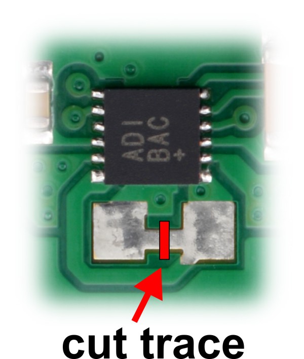 |
Then, you will need to add your own appropriate surface-mount 1206 resistor to these pads.
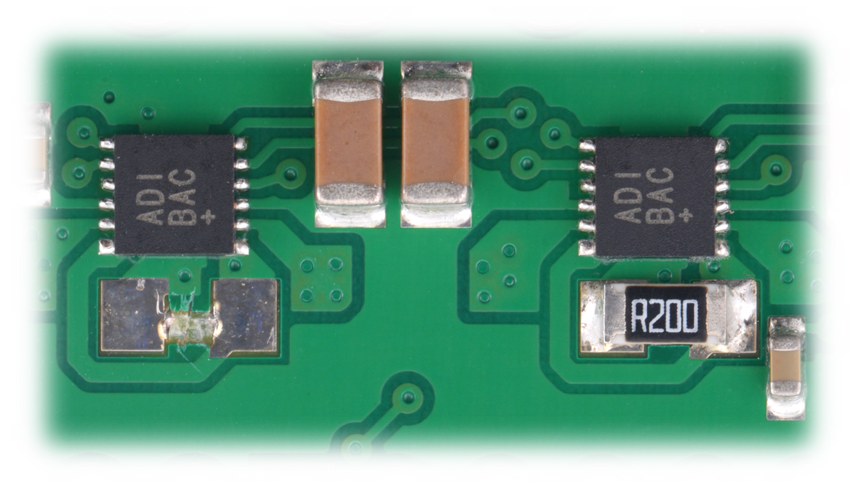 |
Each driver tries to keep the voltage on the SNS pin from exceeding 100 mV, so for example, a 100 mΩ resistor limits the current to 1 A and a 200 mΩ resistor limits it to 0.5 A. For more information on current limiting, see the MAX14870 datasheet (492k pdf).
On the left side of the expansion board is a set of three pins surrounded by a box and labeled “5V”, “GND”, and “VM”. The 5V pin is connected to the Raspberry Pi’s 5V power rail, while the VM pin provides access to the driver board’s motor supply voltage after reverse-voltage protection. If a suitable voltage regulator is connected to these three pins, it can generate 5 V to power the Raspberry Pi from the board’s motor supply voltage.
We suggest using our D24V10F5 or D24V22F5 switching step-down regulators, which have the same 36 V maximum input voltage as the MAX14870 (see below for details on which to choose).
When adding a voltage regulator to the motor driver board, take care to orient it correctly: note that the motor driver board’s VM pin should connect to the regulator’s VIN pin, while the regulator’s VOUT pin should connect to the motor driver board’s 5V pin.
There are several considerations to keep in mind when powering the Raspberry Pi through a voltage regulator in this way:
The D24V10F5 can supply up to 1 A of current to the Raspberry Pi and should work for lower-power models (like the A+) with lighter loads. It can be soldered directly to the motor driver board with a male header to make a compact, permanent connection:
|
|
or plugged into a 3-pin female header soldered to the board for a more modular setup:
|
The D24V22F5 can supply up to 2.5 A and is more suitable for higher-performance Raspberry Pi models (like the Pi 3 B+), especially with demanding workloads or when powering many peripherals. Because of its larger size, it must be connected through longer headers or wires to avoid interference with the terminal blocks.
|
The FAQs page on the Raspberry Pi website has more information on Raspberry Pi power requirements.
The MAX14870 datasheet recommends a maximum continuous current of 2.5 A. However, the chip by itself will typically overheat at lower currents. In our tests, a continuous current of 1.7 A per channel was sustainable for many minutes without triggering a thermal shutdown.
The actual current you can deliver will depend on how well you can keep the motor driver cool. The driver’s printed circuit board is designed to help with this by drawing heat out of the motor driver chip. PWMing the motor will introduce additional heating proportional to the frequency.
This product can get hot enough to burn you long before the chip overheats. Take care when handling this product and other components connected to it.
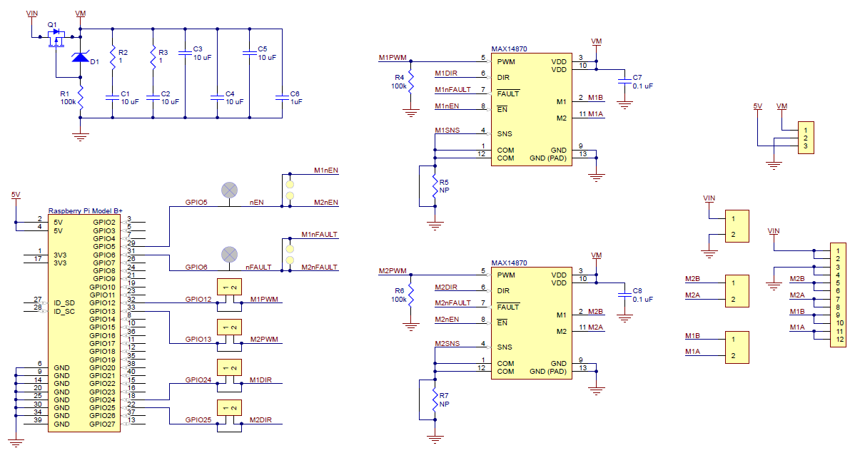 |
Schematic diagram for the Dual MAX14870 Motor Driver for Raspberry Pi. |
|---|
This schematic is also available as a downloadable pdf (134k pdf).
| Size: | 1.7″ × 0.65″1 |
|---|---|
| Weight: | 12 g |
| Motor driver: | MAX14870 (x2) |
|---|---|
| Motor channels: | 2 |
| Minimum operating voltage: | 4.5 V |
| Maximum operating voltage: | 36 V |
| Continuous output current per channel: | 1.7 A2 |
| Peak output current per channel: | 2.5 A |
| Maximum PWM frequency: | 50 kHz |
| Reverse voltage protection?: | Y |
| Partial kit?: | N |
| PCB dev codes: | rpe04a |
|---|---|
| Other PCB markings: | 0J11123 |
This DXF drawing shows the locations of all of the board’s holes.
Maxim Integrated’s product page for the MAX14870, where you can find the latest datasheet and additional resources.
This Python library for the Raspberry Pi makes it easy to interface with a Pololu Dual MAX14870 Motor Driver for Raspberry Pi and use it to drive a pair of brushed DC motors. An example program is included with the library.
No FAQs available.
For my birthday, I am excited to share two new products to help get your projects moving: dual motor driver boards for Arduino and for Raspberry Pi...