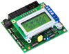
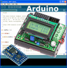
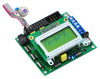
Orangutan LV-168 Robot Controller

The Orangutan LV-168 is a full-featured controller for low-voltage robots. Thanks to a step-up voltage regulator, you can power this Orangutan with two or three 1.2-1.5 V batteries while maintaining 5 V operation for its Atmel mega168 AVR microcontroller and your sensors. A pair of discrete, low-voltage H-bridges deliver up to 2 A continuous per channel to get the most power out of low-voltage motors.
| Description | Specs (17) | Pictures (5) | Resources (25) | FAQs (3) | On the blog (1) | Distributors (0) |
|---|
Documentation and other information
-
Pololu Orangutan SV-xx8 and LV-xx8 User’s Guide (Printable PDF)
User’s guide for the Pololu Orangutan SV-168, SV-328, and LV-168 robot controllers.
-
Pololu AVR Programming Quick Start Guide (Printable PDF)
This guide explains how to get started programming your Orangutan or 3pi Robot in Windows, Linux or Mac OS X. It covers setting up an AVR development environment (Atmel Studio for Windows users), installing the Pololu AVR C/C++ Library, and setting up the Pololu USB AVR Programmer.
-
Pololu AVR C/C++ Library User’s Guide (Printable PDF)
Information about installing and using the C/C++ libraries provided for use with Pololu products.
-
Pololu AVR Library Command Reference (Printable PDF)
A reference to commands provided in the Pololu C/C++ and Arduino libraries for the AVR.
-
Programming Orangutans and the 3pi Robot from AVR Studio 4
Guide for programming Orangutans and the 3pi robot from the Atmel’s older AVR Studio 4 IDE. It covers installing the Pololu AVR C/C++ Library, and setting up the Pololu USB AVR Programmer.
-
Programming Orangutans and the 3pi Robot from the Arduino Environment (Printable PDF)
Guide to making the Arduino IDE compatible with the 3pi robot and the Orangutan SV-328, Orangutan LV-168, and Baby Orangutan B robot controllers, including Arduino libraries for interfacing with all of their on-board hardware.
-
Application Note: Using the Motor Driver on the 3pi Robot and Orangutan Robot Controllers (Printable PDF)
Detailed information about the 3pi Robot, Orangutan SV-328/168 and LV-168, and Baby Orangutan B motor drivers, including truth tables and sample code.
-
Application Note: MLX90614ESF SMBus Communication with Orangutan Robot Controllers (Printable PDF)
A guide for implementing the SMBus (I²C-compatible) protocol for the MLX90614ESF temperature sensor on the AVR-based Orangutan robot controller series. The guide includes sample code for taking temperature readings.
File downloads
-
Pololu AVR Development Bundle for Windows (12MB exe)
This bundle contains all the Pololu software you need to get started programming AVRs in Windows: the Pololu AVR C/C++ Library, the Pololu USB AVR Programmer drivers and software, and the Pololu Orangutan SVP drivers. We recommend installing Atmel Studio 7.0 before installing this bundle.
-
Orangutan LV-168 quick-start sheet and schematic (256k pdf)
-
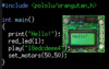
AVR Studio 4 test program for the Orangutan LV-168 (69k zip)
C code for the mega168: This is the program used to test each Orangutan LV-168 before it ships and is part of the program that comes pre-loaded on each Orangutan LV-168. It interfaces with all of the on-board hardware and can be used as a starting point for your own programs. This program requires the Pololu AVR library (libpololu). Please see the Orangutan LV-168 user’s guide for more information about using this test program.
-
AVR Studio 4 demo project #1 for the Orangutan SV-168 and LV-168 (14k zip)
C code for the mega168: This project demonstrates the fundamentals of using I/O lines on a mega168. Each line of the source code is commented, and there is a short tutorial in comments at the start of main() on using AVR I/O and on C bit-logic. The program will alternately flash the two user LEDs until you ground the general-purpose I/O pin PD0 (the right-most of the eight user I/O lines at the top of the board). Grounding pin PD0 will cause the program to pulse the buzzer pin instead of the LED pins, causing the buzzer to play a note. While intended for use on the Orangutan SV-168 and LV-168, this program will run on the Baby Orangutan B-168 and can serve as a useful example on how to use the ATmega48/168 I/O lines. It will run on the Baby Orangutan B-328 with some minor modifications.
-
AVR Studio 4 demo project #2 for the Orangutan SV-168 and LV-168 (16k zip)
C code for the mega168: This is a slightly more advanced program that demonstrates triggering actions with the user buttons and controlling the buzzer using one of the mega168’s hardware PWMs (as opposed to the processor-intensive software buzzer control we used in Demo 1). The program will cause the buzzer to play while the user buttons are held down. The button held down determines the frequency of the note the buzzer plays.
-
AVR Studio 4 demo project #3 for the Orangutan LV-168 (29k zip)
C code for the mega168: This project demonstrates analog-to-digital conversion, use of the LCD, and control of the motor ports. Specifically, it uses the mega168’s analog-to-digital converter to monitor the position of the user potentiometer. It displays the potentiometer’s position on the LCD and drives the two motor ports based on this position.
-
Sample AVR Studio 4 project for the ATmega168 to blink an LED (9k zip)
This is a sample AVR Studio 4 project that will blink an LED on an Orangutan with an ATmega168 microcontroller: Orangutan mega168, Orangutan LV-168, Orangutan SV-168, Baby Orangutan mega168, and Baby Orangutan B-168.
-
AVR Studio 4 demo project #4 for the Orangutan LV-168 (29k zip)
C code for the mega168: This project demonstrates the use of the mega168’s UART, interrupts, and reading the on-board temperature sensor. To make full use of this demo, you will need a source capable of producing logic-level (TTL) serial transmissions at 115.2 kbps. The Pololu Orangutan USB programmer can be such a source if you switch the blue shorting block to the USB-to-serial-adapter position and connect its TX pin to pin PD0 on your Orangutan LV-168. Don’t forget to also connect the programmer’s ground pad (labeled G) to ground on your Orangutan. Then start up a terminal program such as Hyperterm or Tera Term Pro, connect to your serial adapter’s COM port, set the baud for 115.2 kbps, and start typing characters. You should see the characters appear on the top row of your Orangutan LV-168’s LCD while the bottom row displays the output of your board’s temperature sensor. If you touch the board near the temperature sensor, you should see this reading rise.
-
MCP9701 datasheet (522k pdf)
Datasheet for the MCP9701 temperature sensor used on the Orangutan LV-168.
Recommended links
-
WinAVR
A free, open-source suite of development tools for the AVR family of microcontrollers, including the GNU GCC compiler for C/C++.
-
AVR Studio 4
The older version of Atmel’s free integrated development environment (IDE) for AVRs, which is no longer supported by Atmel.
-
ATmega168 documentation
Microchip’s product page for the ATmega168.
-
AVR Libc Home Page
The web site for AVR Libc, which is the standard library of functions that you can use with C and C++ on the AVR.
-
GCC, the GNU Compiler Collection
Documentation for GCC, including the AVR GCC C/C++ compilers.
-
Pololu A-Star and Orangutan Forum Section
The A-Star and Orangutan discussion section of the Pololu Robotics Forum.
-
AVR Freaks
AVR community with forums, projects, and AVR news.
-
Tutorial: AVR Programming on the Mac
Customer Michael Shimniok has written a guide to programming AVRs (the Orangutan LV-168, specifically) using the Mac.
Related products


Home | Forum | Blog | Support | Ordering Information | Lists | Distributors | BIG Order Form | About | Contact
© 2001–2026 Pololu Corporation
