

This is a merged information page for Item #713.
View normal product page.
Pololu item #:
713
Brand:
Pololu
Status:
Active

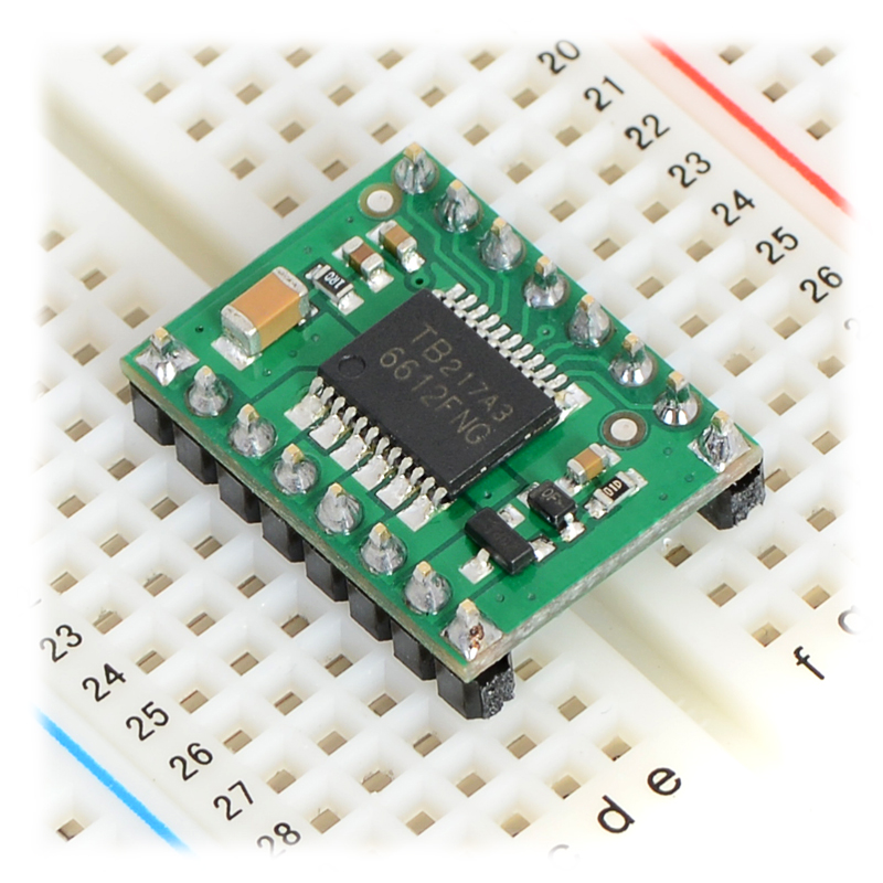
This tiny board is an easy way to use Toshiba’s TB6612FNG dual motor driver, which can independently control two bidirectional DC motors or one bipolar stepper motor. A recommended motor voltage of 4.5 V to 13.5 V and peak current output of 3 A per channel (1 A continuous) make this a great motor driver for low-power motors.
 Compare all products in Brushed DC Motor Drivers.
|
TB6612FNG dual motor driver carrier (latest version with all ceramic capacitors). |
|---|
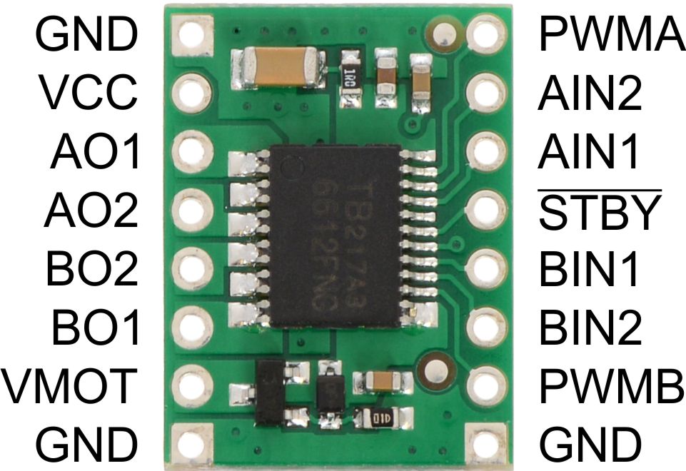 |
TB6612FNG dual motor driver carrier, top view with pads labeled. |
|---|
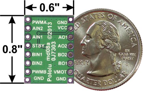 |
TB6612FNG dual motor driver carrier, bottom view with dimensions. |
|---|
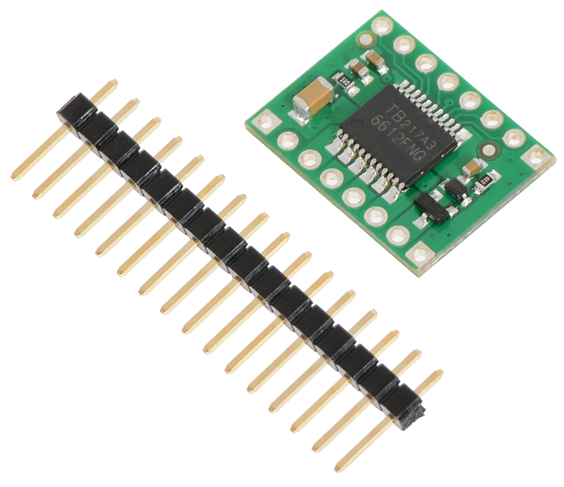 |
TB6612FNG dual motor driver carrier with included header pins. |
|---|
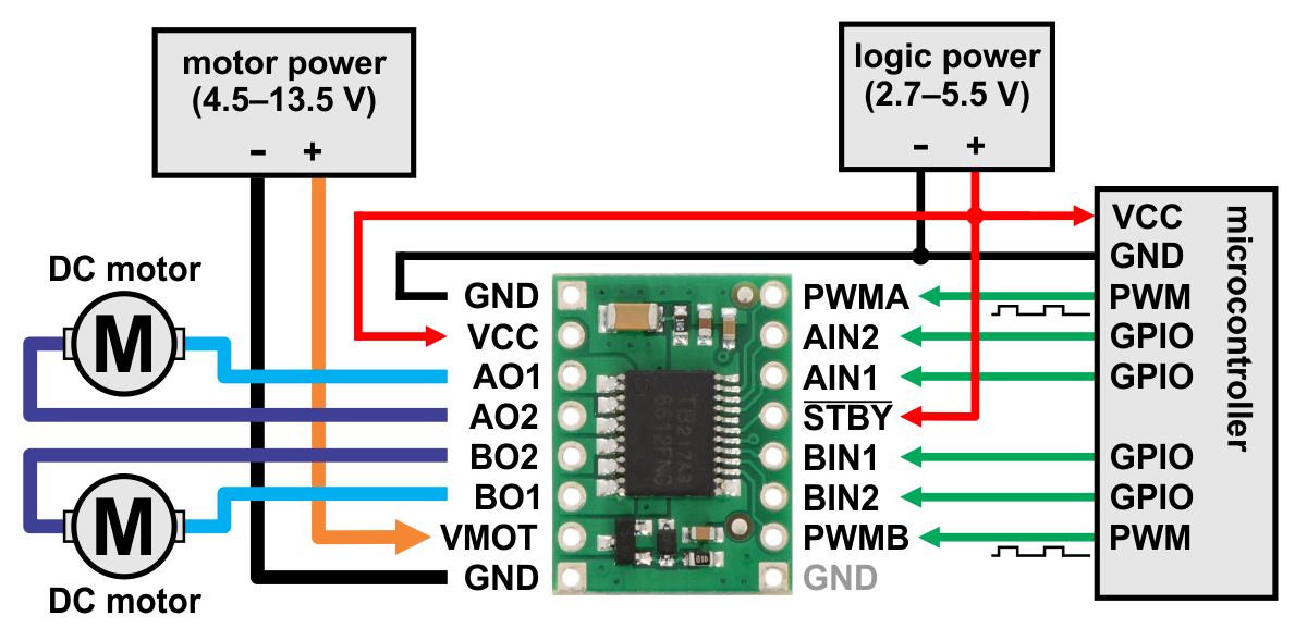 |
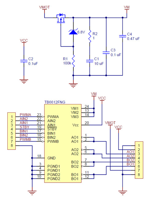
Minimal wiring diagram for connecting a microcontroller to a TB6612FNG dual motor driver carrier. |
|---|
 |
TB6612FNG dual motor driver carrier on a breadboard. |
|---|
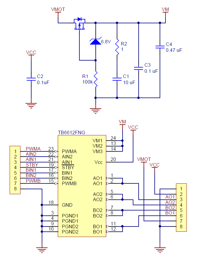 |
TB6612FNG dual motor driver carrier schematic diagram (latest version with all ceramic capacitors). |
|---|
|
The TB6612FNG (308k pdf) is a great dual motor driver that is perfect for interfacing two small DC motors such as our micro metal gearmotors to a microcontroller, and it can also be used to control a single bipolar stepper motor. The MOSFET-based H-bridges are much more efficient than the BJT-based H-bridges used in older drivers such as the L298N and Sanyo’s LB1836M, which allows more current to be delivered to the motors and less to be drawn from the logic supply (the LB1836 still has the TB6612 beat for really low-voltage applications). Our little breakout board gives you direct access to all of the features of the TB6612FNG and adds power supply capacitors and reverse battery protection on the motor supply (note: there is no reverse protection on the Vcc connection).
|
In a typical application, power connections are made on one side of the board and control connections are made on the other. All of the control inputs are internally pulled low. Each of the two motor channels has two direction control pins and a speed control pin that accepts a PWM input with a frequency of up to 100 kHz. The STBY pin must be driven high to take the driver out of standby mode.
|
TB6612FNG dual motor driver carrier on a breadboard. |
|---|
The distance between the header rows on the PCB is 0.1" smaller than a standard 0.6" DIP package (e.g. the Baby Orangutan), but the pin spacing allows it to conveniently fit in 0.1" breadboards and perfboards.
For a more advanced motor controller based on this driver, please consider the qik 2s9v1 dual serial motor controller. For a robot controller based on this driver, please consider the Baby Orangutan, Orangutan SV-328, Orangutan SVP-1284, and 3pi robot, which connect the TB6612 to a user-programmable AVR microcontroller. For a similar motor driver that is easy to use with Arduinos, consider our DRV8835 dual motor driver shield, and for a similar motor driver with a much higher maximum operating voltage, consider our A4990 dual motor driver carrier.
|
Minimal wiring diagram for connecting a microcontroller to a TB6612FNG dual motor driver carrier. |
|---|
Motor, motor power, and logic power connections are made on one side of the board and control connections are made on the other. The STBY pin is pulled low internally, putting the TB6612FNG into a low-power sleep mode by default, and must be driven high (2.7 V – 5.5 V) in order to enable the driver.
The AO1 and AO2 pins form one motor channel while the BO1 and BO2 pins form the other. The state of each output is controlled by a corresponding inputs (PWMA, AIN1, AIN2, and PWMB, BIN1, BIN2 respectively). See the truth tables in the TB6612FNG datasheet (308k pdf) for more information on how the inputs affect the driver outputs.
The TB6612 motor driver used on the carrier board has a peak current rating of 3 A per channel. The peak ratings are for quick transients (e.g. when a motor is first turned on), and the continuous rating of 1 A is dependent on various conditions, such as the ambient temperature. The actual current you can deliver will depend on how well you can keep the motor driver cool. The carrier’s printed circuit board is designed to draw heat out of the motor driver chip, but performance can be improved by adding a heat sink.
This product can get hot enough to burn you long before the chip overheats. Take care when handling this product and other components connected to it.
A 1×16-pin breakaway 0.1″ male header strip is included with the TB6612FNG motor driver carrier. This strip can optionally be soldered to the carrier board so that it can be used with perfboards, solderless breadboards, or 0.1″ female connectors. (The headers might ship as two 1×8 pieces or as a single 1×16 piece that can be broken in half.)
|
 |
This schematic is also available as a downloadable pdf (85k pdf).
| Size: | 0.60" x 0.80" |
|---|---|
| Weight: | 1.5 g |
| Motor driver: | TB6612FNG |
|---|---|
| Motor channels: | 2 |
| Minimum operating voltage: | 4.5 V1 |
| Maximum operating voltage: | 13.5 V |
| Continuous output current per channel: | 1 A |
| Peak output current per channel: | 3 A |
| Continuous paralleled output current: | 2 A |
| Maximum PWM frequency: | 100 kHz |
| Minimum logic voltage: | 2.7 V |
| Maximum logic voltage: | 5.5 V |
| Reverse voltage protection?: | Y |
Detailed information about the 3pi Robot, Orangutan SV-328/168 and LV-168, and Baby Orangutan B motor drivers, including truth tables and sample code.
Printable schematic diagram for the TB6612FNG-dual motor driver carrier.
This DXF drawing shows the locations of all of the board’s holes.
No FAQs available.

Congratulations to Team Anveshak from IIT Madras, who took first place at the 2019 Indian Rover Challenge! The IRC is a robotics and space...
One of our forum members, gchristopher, posted about his 3D-printed mecanum wheel rover. The rover uses our D24V10F5 5V regulator and some of our...
This PID line follower, originally featured in this Let’s Make Robots post by user Enigmerald, uses our 5" Robot Chassis along with 30:1 MP micro...
Pololu forum user Mert Öztoprak posted this parts list and the short video above of a Android-controlled mini sumo robot called “Karafatma”.