
This is a merged information page for Item #5083.
View normal product page.
Pololu item #:
5083
Brand:
Pololu
Status:
Active and Preferred

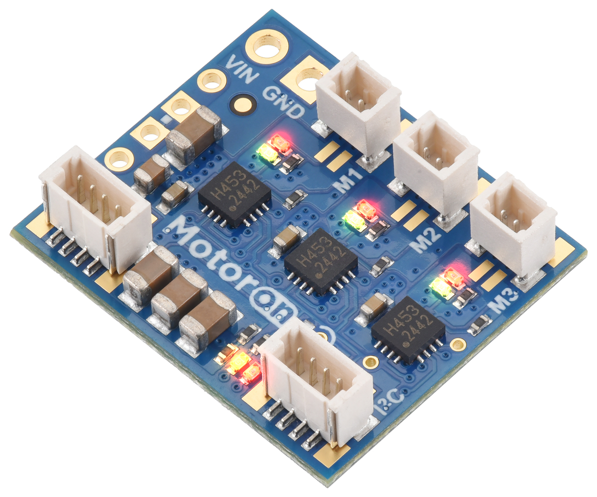
The Motoron M3T453 Triple I²C Motor Controller offers a compact solution for controlling three DC motors through an I²C interface. Multiple Motoron controllers can be connected to the same I²C bus, making it easy to expand a system with additional motors. The M3T453 supports motor supply voltages from 4.5 V to 44 V and can deliver continuous output currents up to 0.8 A per motor. This version has JST SH-style connectors for the I²C and motor connections. It does not include a motor power connector.
 Compare all products in Motoron M3T453 Triple Motor Controllers.
|
Motoron M3T453 Triple I²C Motor Controller with JST SH-Style Connectors. |
|---|
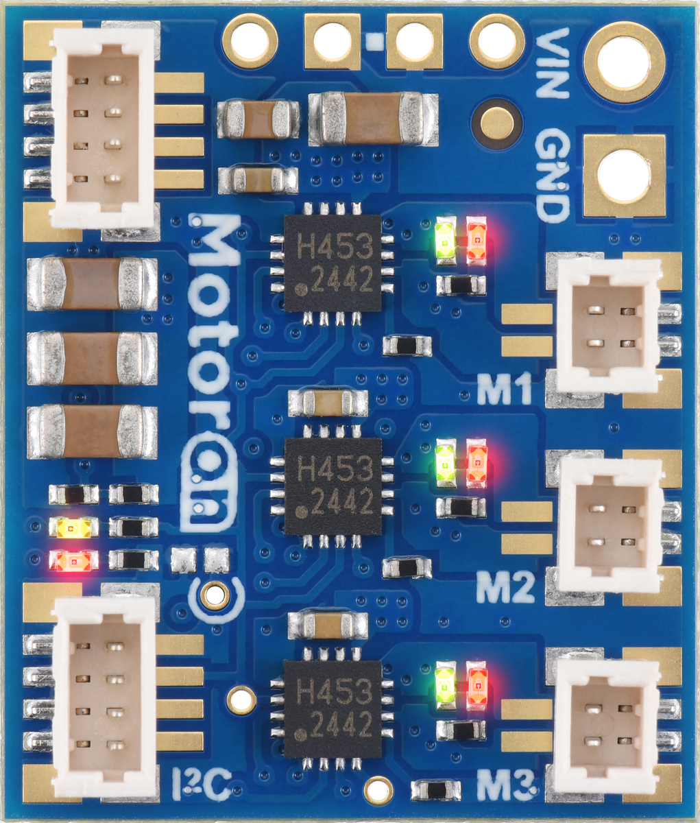 |
Motoron M3T453 Triple I²C Motor Controller with JST SH-Style Connectors (No VIN Connector), top view. |
|---|
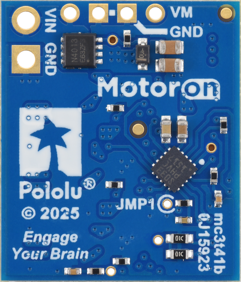 |
Motoron M3T453 Triple I²C Motor Controller with JST SH-Style Connectors, bottom view. |
|---|
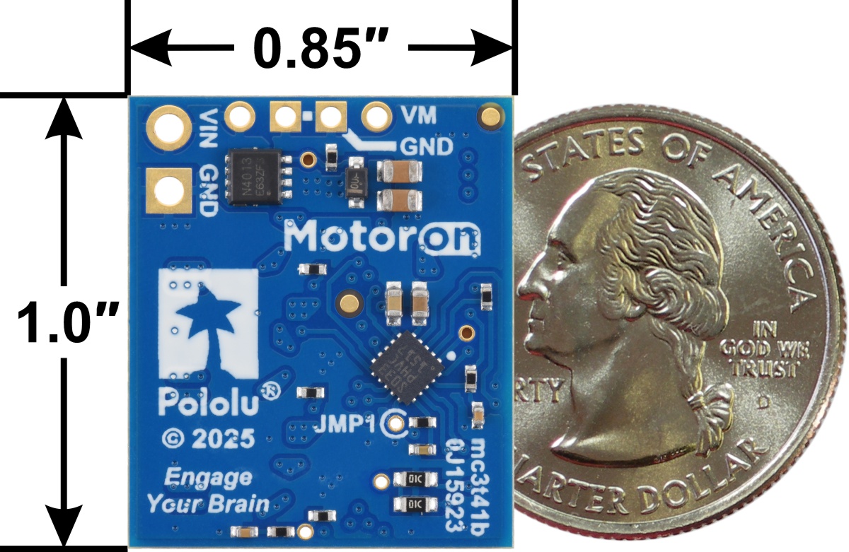 |
Motoron M3T453 Triple I²C Motor Controller with JST SH-Style Connectors, bottom view with basic dimensions and a US quarter for size reference. |
|---|
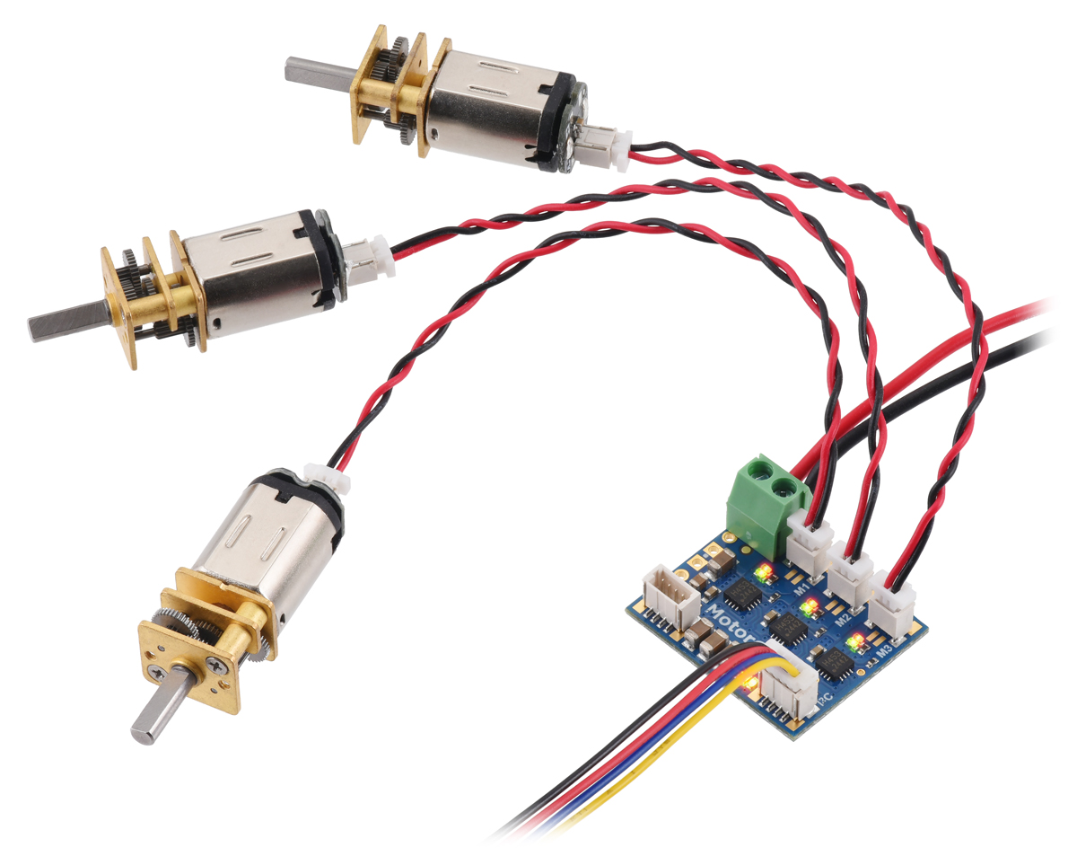 |
Using a Motoron M3T453 Triple I²C Motor Controller with JST SH-Style Connectors to control three motors. |
|---|
 |
Typical wiring diagram for connecting a microcontroller to a Motoron M3T453 Triple I²C Motor Controller with JST SH-Style Connectors. |
|---|
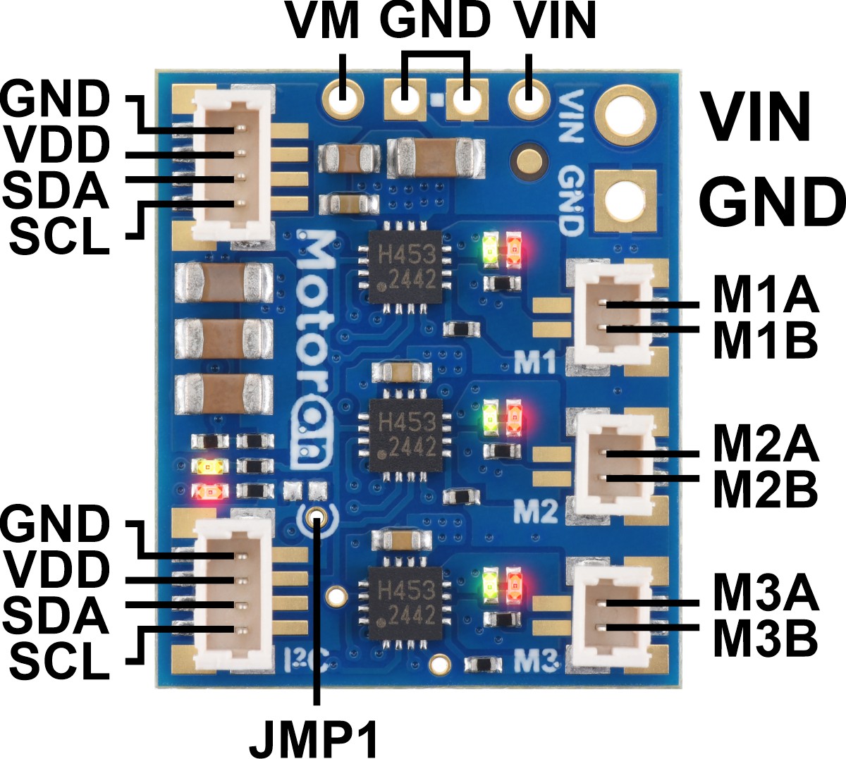 |
Pinout of the Motoron M3T453 Triple I²C Motor Controller with JST SH-Style Connectors. |
|---|
The Motoron M3T453 controllers make it easy to control three bidirectional, brushed DC motors using an I²C interface. These compact boards support motor supply voltages from 4.5 V to 44 V and can deliver output currents up to 0.8 A continuous (2 A peak) per motor. Multiple Motoron controllers can be configured to work on a single I²C bus, allowing independent control of many motors. Unlike most of our motor drivers, the Motoron does not require any PWM outputs or timers on your microcontroller. Instead, only a single I²C interface is needed regardless of how many Motorons you connect.
Four M3T453 versions are available to provide different connector options:
|
Typical wiring diagram for connecting a microcontroller to a Motoron M3T453 Triple I²C Motor Controller with JST SH-Style Connectors. |
|---|
This version of the M3T453 has JST SH-style connectors for the I²C and motor connections, and it ships without a VIN connector. Motor power (VIN) can be supplied by soldering wires or your own connectors to the smaller 0.1″-pitch through-holes along the top edge of the board or the larger 3.5mm-pitch holes along the right side of the board. The smaller holes are compatible with 0.1″ male headers and female headers, and the larger holes are compatible with 3.5mm terminal blocks.
|
|
The I²C connection to the Motoron can be made through either of the board’s two 4-pin connectors, which work with our 4-pin JST SH-style cables and are compatible with SparkFun’s Qwiic and Adafruit’s STEMMA QT (the second connector can be used to chain additional Motorons or other I²C devices). The motor connectors are compatible with our 2-pin JST SH-style cables and JST SH-Style Connector Board for Micro Metal Gearmotors.
|
Using a Motoron M3T453 Triple I²C Motor Controller with JST SH-Style Connectors to control three motors. |
|---|
The tables below list the members of the Motoron family and show the key differences among them. Each type is available in several versions to provide different options for the through-hole connectors: they can be purchased as an assembled product with connectors soldered in, as a kit with connectors included but not soldered in, or (for Arduino and Raspberry Pi expansions) as a standalone board without connectors.
| Motoron motor controllers micro versions |
|||||
 M3T453 w/JST connectors  M3T453 w/0.1″ headers |
 M1T550 M1U550 |
 M2T550 M2U550 |
 M1T256 M1U256 |
 M2T256 M2U256 |
|
|---|---|---|---|---|---|
| Control interface: | I²C | I²C or UART serial | |||
| Motor channels: | 3 (triple) | 1 (single) | 2 (dual) | 1 (single) | 2 (dual) |
| Minimum motor supply voltage: |
4.5 V | 1.8 V | 4.5 V | ||
| Absolute max motor supply voltage: |
44 V | 22 V | 48 V | ||
| Recommended max nominal battery voltage: |
32 V | 16 V | 36 V | ||
| Max continuous current per channel: |
0.8 A | 1.8 A | 1.6 A | 2.2 A | 1.8 A |
| Logic voltage range: | 3.0 V to 5.5 V | 3.0 V to 4.9 V(1) | 3.0 V to 5.5 V | ||
| Current sensing: | channels 1 & 2 only | – | – | – | – |
| Current limiting: | – | – | – | – | – |
| Available versions with I²C: |
|||||
| Available versions with UART serial: |
– | ||||
| Price: | $18.95 – $19.95 | $12.49 – $13.49 | $15.95 – $16.95 | $16.95 – $17.95 | $23.95 – $24.95 |
| 1 The M1x550 and M2x550 are not recommended for use with 5V nominal logic. | |||||
| Motoron motor controllers Arduino and Raspberry Pi form factor versions |
||||||
 M3S550  M3H550 |
 M3S256  M3H256 |
 M2S24v14  M2H24v14 |
 M2S24v16  M2H24v16 |
 M2S18v18  M2H18v18 |
 M2S18v20  M2H18v20 |
|
|---|---|---|---|---|---|---|
| Control interface: | I²C | |||||
| Motor channels: | 3 (triple) | 2 (dual) | ||||
| Minimum motor supply voltage: |
1.8 V | 4.5 V | 6.5 V | |||
| Absolute max motor supply voltage: |
22 V | 48 V | 40 V | 30 V | ||
| Recommended max nominal battery voltage: |
16 V | 36 V | 28 V | 18 V | ||
| Max continuous current per channel: |
1.7 A | 2 A | 14 A | 16 A | 18 A | 20 A |
| Logic voltage range: | M3S550 3.1 V to 5.5 V |
3.0 V to 5.5 V | 3.0 V to 5.5 V | |||
| M3H550 3.0 V to 4.9 V(1) |
||||||
| Current sensing/limiting: | – | – | ||||
| Available versions for Arduino: |
M3S550 | M3S256 | M2S24v14 | M2S24v16 | M2S18v18 | M2S18v20 |
| Available versions for Raspberry Pi: |
M3H550 | M3H256 | M2H24v14 | M2H24v16 | M2H18v18 | M2H18v20 |
| Price: | $20.95 – $30.95 | $34.95 – $44.95 | $59.95 – $69.95 | $79.95 – $89.95 | $59.95 – $69.95 | $79.95 – $89.95 |
| 1 The M3H550 is not recommended for use with 5V nominal logic. | ||||||
| Size: | 0.85″ × 1.0″ |
|---|---|
| Weight: | 2.4 g |
| Channels: | 3 |
|---|---|
| Model: | Motoron M3T453 |
| Control interface: | I²C |
| Minimum operating voltage: | 4.5 V |
| Maximum operating voltage: | 44 V1 |
| Continuous output current per channel: | 0.8 A |
| Peak output current per channel: | 2 A2 |
| Minimum logic voltage: | 3.0 V |
| Maximum logic voltage: | 5.5 V |
| Reverse voltage protection?: | Y3 |
| PCB dev codes: | mc3t41b |
|---|---|
| Other markings: | 0J15923 |
User’s manual for the Pololu Motoron Motor Controllers.
This DXF drawing shows the locations of all of the board’s holes.
This DXF drawing shows the locations of all of the board’s holes.
No FAQs available.
We’re pleased to announce the release of our new Motoron M3T453 triple motor controllers. These compact boards make it easy to...