Electronics » Regulators and Power Supplies » Step-Up (Boost) Voltage Regulators »
Pololu Adjustable Boost Regulator 4-25V

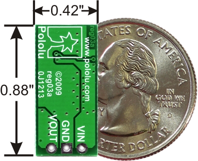
This powerful, adjustable boost regulator can generate an output voltage as high as 25 V from an input voltage as low as 1.5 V, all in a compact, 0.42″ x 0.88″ x 0.23″ package. A trimmer potentiometer lets you set the boost regulator’s output voltage to a value between 4 and 25 V.

| Description | Specs (11) | Pictures (7) | Resources (3) | FAQs (0) | On the blog (1) |
|---|
Overview
 |
The Pololu adjustable boost regulator is a very flexible switching regulator (also called a switched-mode power supply, SMPS, or DC-to-DC converter) that can generate voltages higher than its input voltage. We offer two adjustable ranges: approximately 2.5 V to 9.5 V and 4 V to 25 V. The output voltage can be set using the trimmer potentiometer in the upper-right corner of the board. The input voltage range is 1.5 V to 16 V (the input voltage should be kept below the output voltage). The integrated 2 A switch allows for output currents high enough to drive small motors, as in our 3pi robot, and allows large voltage gains, such as obtaining 24 V from two NiMH or NiCd cells.
Some example applications include:
- Powering 5 V or 3.3 V systems from lower-voltage batteries
- Powering 5 V subsystems (e.g. sensors) in lower-voltage (e.g. 3.3 V) systems
- Achieving consistent actuator operation when powered by fluctuating batteries
- Powering high-brightness LEDs or a large number of LEDs in series
Note: For high-volume applications, this product can be customized with fixed output voltages ranging from 2 V to 30 V.
 |
Feature summary
- input voltage: 1.5 V to 16 V
- output adjustable from 2.5 V to 9.5 V or 4 V to 25 V
- 750 kHz switching frequency
- 2 A switch (and input) limit
- integrated over-temperature and over-current shutoff
- typical efficiency of 80-90% when doubling voltage and with 100-500 mA output
- small size: 10.7 x 22.4 x 5.8 mm (0.42″ x 0.88″ x 0.23″)
- weight without header pins: 1.6 g (0.06 oz)
Using the Boost Regulator
 |
Connections
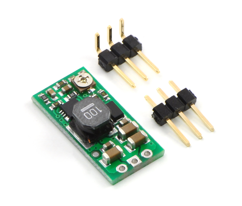
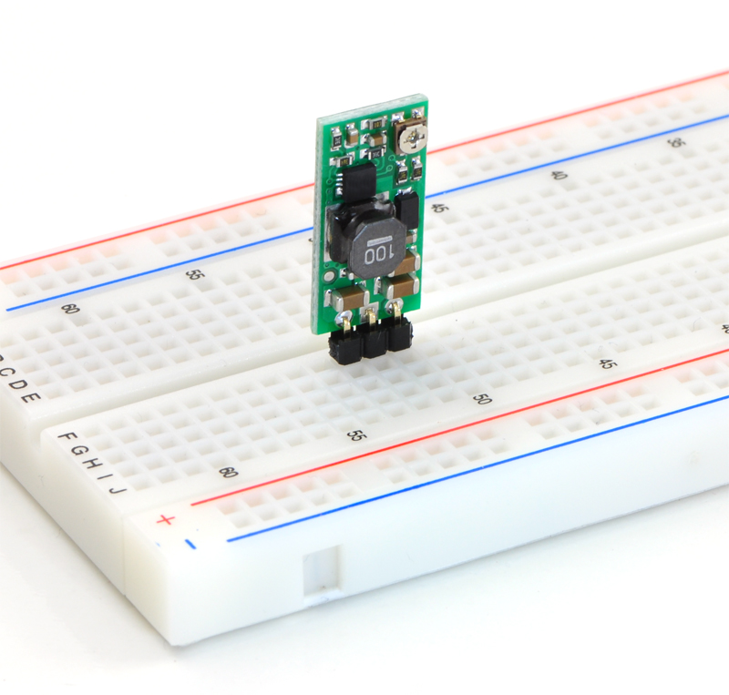
The boost regulator has just three connections: the input voltage, ground, and the output voltage. These three connections are labeled on the back side of the PCB, and they are arranged with a 0.1″ spacing along the edge of the board for compatibility with standard solderless breadboards and perfboards and connectors that use a 0.1″ grid. You can solder wires directly to the board or solder in either the 3×1 straight male header strip or the 3×1 right-angle male header strip that is included.
Setting the output voltage
The output voltage can be adjusted using a meter and a light load (e.g. a 10 kΩ resistor). Turning the potentiometer clockwise increases the output voltage. The output voltage can be affected by a screwdriver touching the potentiometer, so the output measurement should be done with nothing touching the potentiometer.
Warning: You should be careful not to use an input voltage that exceeds the output voltage setting, so we recommend setting the output voltage with the input voltage around or below 2.5 V (e.g. using one or two alkaline batteries). Note that the potentiometer has no physical end stops, which means that the wiper can be turned 360 degrees and into an invalid region in which the output voltage is set to approximately 2.5 V (for both the 2.5 V to 9.5 V and 4 V to 25 V versions).
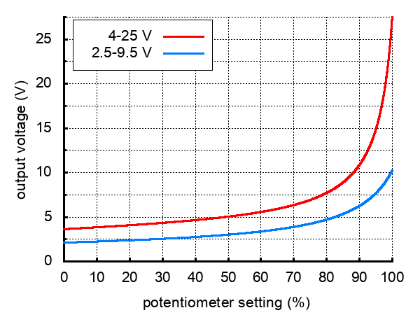 |
Output voltage settings for the adjustable boost regulators. |
|---|
The absolute limit for the input voltage is double the output voltage setting. For example, if the output is set to 6 V, the input must not exceed 12 V. Once the input exceeds the output set point, the output voltage will rise with the input voltage since the input is connected to the output through an inductor and a diode.
Note: The trimmer potentiometer is not rated for continual adjustment back and forth; the intended application is to set the output voltage a few times in its life.
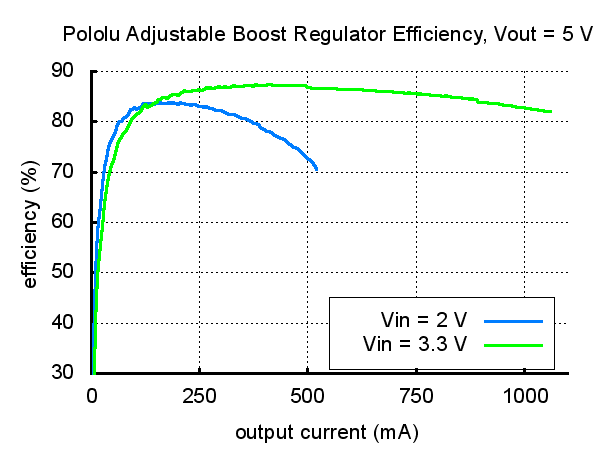
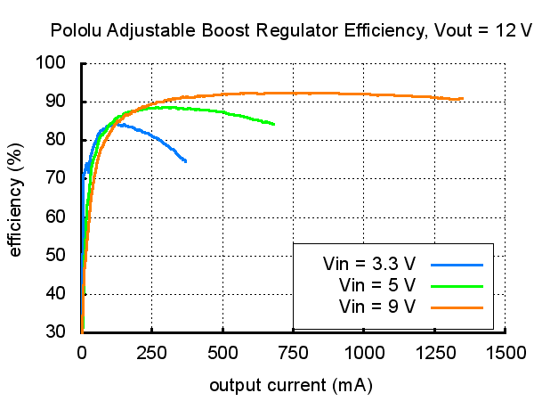
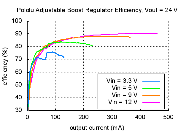
Efficiency and available output current
The available output current depends on the input and output voltages. The input current is limited to approximately 2 A, and, as shown in the graphs below, the efficiency is typically 80% to 90%. Therefore, the maximum available current will be approximately 800 mA when doubling the input voltage and approximately 400 mA when quadrupling the input voltage. At high output powers, the 20% lost in the regulator will cause substantial heating, which can limit the available output power (the regulator will automatically shut off if its internal temperature gets too high). At low output currents and high input and output voltages, the efficiency drops closer to 50%, though the lower power involved prevents heating from being an issue. Some output voltages shown in the efficiency graphs below can only be achieved using the 4-25V adjustable boost regulator.
 |
 |
 |
LC Voltage Spikes
When connecting voltage to electronic circuits, the initial rush of current can cause voltage spikes that are much higher than the input voltage. If these spikes exceed the regulator’s absolute maximum voltage (16 V), the regulator can be destroyed. If you are connecting more than approximately 10 V or your power leads or supply has high inductance (e.g. your input leads are longer than a few inches), we recommend soldering a 33μF or larger electrolytic capacitor close to the regulator between VIN and GND. The capacitor should be rated for at least 25 V.
More information about LC spikes can be found in our application note, Understanding Destructive LC Voltage Spikes.
People often buy this product together with:
 |
Pololu Adjustable Boost Regulator 2.5-9.5V |
Related products


Home | Forum | Blog | Support | Ordering Information | Wish Lists | Distributors | BIG Order Form | About | Contact
© 2001–2024 Pololu Corporation
