Electronics » Computer Interface »
TPS2113A Power Multiplexer Carrier with USB Micro-B Connector

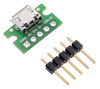
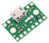
This breakout board for Texas Instruments’s TPS2113A autoswitching power multiplexer allows you to select which of two power sources is connected to a load while blocking reverse current into either of the sources. It has an adjustable current limit that can be set as high as 2 A and an adjustable switching threshold. Each input power rail on the multiplexer can be supplied with 2.8 V to 5.5 V, and the board also breaks out a USB Micro-B connector that can be used to supply one of the rails.
 Compare all products in Computer Interface or Electronics Prototyping or Switches, Buttons, and Relays.
| Description | Specs (7) | Pictures (9) | Resources (2) | FAQs (0) | On the blog (1) |
|---|
 |
Overview
The Texas Instruments TPS2113A autoswitching power multiplexer allows you to switch seamlessly between two power sources of 2.8 V to 5.5 V while blocking reverse current into either source. The power multiplexer (or mux) has an adjustable current limit that can be set as high as 2 A and an adjustable switching threshold that helps reduce output voltage droop when switching. Each input channel is controlled by an internal MOSFET switch, so the mux avoids the voltage drop that occurs when diodes are used to OR multiple power supplies together.
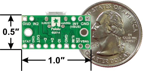
The TPS2113A makes a great addition to any project that needs to be able to transition between two sources like USB and external power, but its small size makes it difficult for a student or hobbyist to use. This carrier breaks out all of the chip’s features to 0.1″-spaced pins, making it easy to use with standard solderless breadboards. In addition, the board serves as a breakout for a USB Micro-B connector that can be used to supply one of the input power rails.
By default, the TPS2113A operates in autoswitching mode, which means that it will automatically select the source that has a higher voltage, but the VSNS pin can be used to maintain IN1 as the selected source until it falls below a configurable switching threshold, making IN1 the primary or preferred source. The board ships with USB power connected to IN1, which enables the common application of having a device that can be powered by USB or an external power supply, automatically choosing the appropriate source based on what is connected. USB power can be switched from IN1 to IN2 by cutting a trace and configuring a surface-mount jumper.
Since this board is a carrier for the TPS2113A, we recommend careful reading of the TPS2113A datasheet.
We carry a similar power multiplexer based on the FPF1320 that is smaller, lower-cost, and works at lower voltages, but it has some limitations that make it not as well suited for automatic USB power-switching applications (e.g. the output voltage can drop to 1 V before the FPF1320 switches to the secondary source).
Using the power multiplexer
Pinout
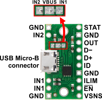 |
| Pin | Description |
|---|---|
| IN1 | Primary power switch input. Can be connected to a 2.8 V to 5.5 V power source. Connected to VBUS by default through surface-mount jumper. The multiplexer will function with IN1 as low as 1.5V as long as IN2 is above 2.8 V. |
| IN2 | Secondary power switch input. Can be connected to a 2.8 V to 5.5 V power source. |
| VBUS | USB 5 V supply. Connected to IN1 by default through surface-mount jumper. |
| OUT | Multiplexed power output. |
| GND | Common ground for power supplies, load, and USB. (All of the board’s GND pins are internally connected with each other and with GND from the USB connector.) |
| VSNS | Switching control input. An internal power FET connects OUT to IN1 if the VSNS voltage is greater than 0.8 V. Otherwise, the FET connects OUT to the higher of IN1 and IN2. This pin is pulled low through an on-board 20 kΩ pull-down resistor, setting the board to autoswitching mode by default. See the Control inputs section below for more details on using this pin to set a switching threshold. |
| EN | Enable input. When driven high, OUT is disconnected from both IN1 and IN2. This pin is pulled low through an on-board 100 kΩ pull-down resistor so the IC is enabled by default. |
| ILIM | Current limit input. An on-board 1 kΩ resistor from ILIM to GND sets the default current limit to 0.5 A nominally, but an external resistor can be added in parallel with it to increase the limit to a maximum of 2 A. |
| STAT | Status output that indicates which input is currently connected to the output. This pin drives low when IN1 is selected and is pulled up to OUT through an on-board 100 kΩ pull-up resistor when IN2 is selected. |
| D− D+ ID |
Signals broken out from USB connector. |
Control inputs
The TPS2113A has three control inputs that can optionally be used to override the default behavior of the device: VSNS (switching operation control), EN (enable), and ILIM (current limit control).
The VSNS pin determines the switching behavior of the device. It is pulled low by default, which results in autoswitching mode (the higher of the two input sources is automatically selected). However, when the voltage on this pin exceeds 0.8 V, the primary input source, IN1, is connected to OUT regardless of the voltages on IN1 and IN2. The precise nature of this 0.8 V threshold in turn makes it possible to use an external resistor to set a desired switching threshold for IN1. By connecting this external resistor between VSNS and IN1, a voltage divider is created with the existing 20 kΩ VSNS pull-down resistor, and the board will select IN1 as long as the output of this voltage divider is greater than 0.8 V. (If it drops below the 0.8 V threshold, the multiplexer reverts to selecting the higher of the two sources.) The value of the added resistor determines the voltage at which the behavior of the multiplexer changes, as defined by the following equation:
``V_text(threshold) = (R/(20\ text(kΩ)) + 1) * 0.8\ text(V)``
The board has a second IN1 pin so that there is a convenient place to connect this switching threshold resistor. For 5 V applications, adding a 100 kΩ resistor works well, since that sets the threshold to 4.8 V. The VSNS input has built-in hysteresis which helps prevent repeated switching from one source to the other.
The EN pin can be driven high to turn off the output and put the TPS2113A in a low-power state. The board is enabled by default.
The ILIM pin is used to set the multiplexer’s current limit by comparing the voltage across a resistor with an internal 0.5V reference. The board includes a 1 kΩ resistor that sets the default current limit to a nominal 0.5 A, but an external resistor can be connected between the ILIM pin and GND to increase the limit to a maximum of 2 A. Such a resistor can conveniently be connected between the ILIM pin and the neighboring GND pin. The following equation shows how the value of the external resistor determines the current limit:
``I_text(limit) = ((1\ text(kΩ))/R + 1) * 0.5\ text(A)``
We can see from this that the 2 A maximum current limit can be achieved by adding a 330 Ω resistor. (Note that the actual current limiting threshold can vary by up to about 0.3 A from the nominal limit; see the datasheet for details.)
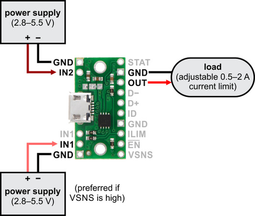
Power connections without USB
If you want to select from between two general power supplies, you can connect one power source across IN1 and GND and the other across IN2 and GND. The voltages on these power inputs can be up to 5.5 V, and the multiplexer will function with IN1 as low as 1.5V as long as IN2 is above 2.8 V. The load should be connected across OUT and GND and should draw no more than 2 A. In this configuration, the power supply connected to IN1 is the primary power source if VSNS is high.
 |
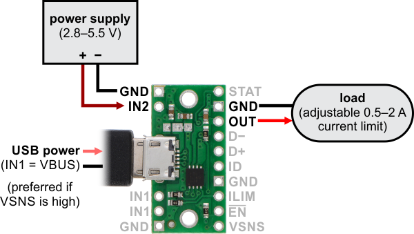
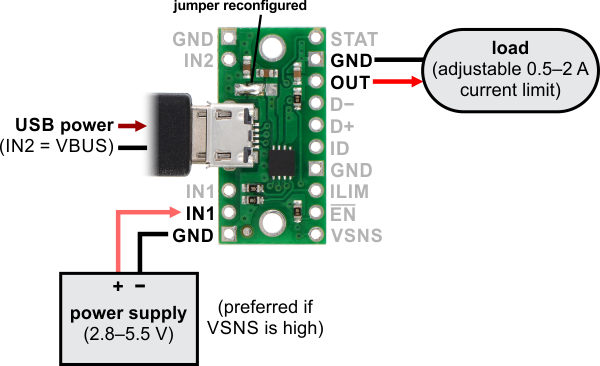
Power connections with USB
The Micro-B USB connector makes it easy to use USB as one of the two power sources. By default, the VBUS line from the USB connector is tied to IN1. This allows you to power your circuit from either USB or an external power source connected to IN2, with USB as the primary power source if VSNS is high.
 |
If you want the external source to be the primary source instead of USB, you can use a hobby knife to cut the trace in the board’s surface-mount jumper that connects the IN1 and VBUS pads, then bridge the VBUS and IN2 pads to connect those two lines together. You can then connect your external source to IN1, making it the preferred supply if VSNS is high.
 |
Warning: It is important to be aware that while this board has three power inputs, two of those three are typically tied together (there are only two independent power inputs to the TPS2113A). As such, you must take care to avoid creating a short circuit between USB power and an external power supply. For example, when the board is in its default configuration (i.e. with VBUS tied to IN1), any external power supply must be connected to IN2; connecting it to IN1 will create a short between this power supply and USB power when USB is connected.
The remaining lines from the USB connector (D−, D+, ID, and GND) are broken out to a set of pins adjacent to OUT, allowing this module to also function as a basic USB Micro-B connector breakout board.
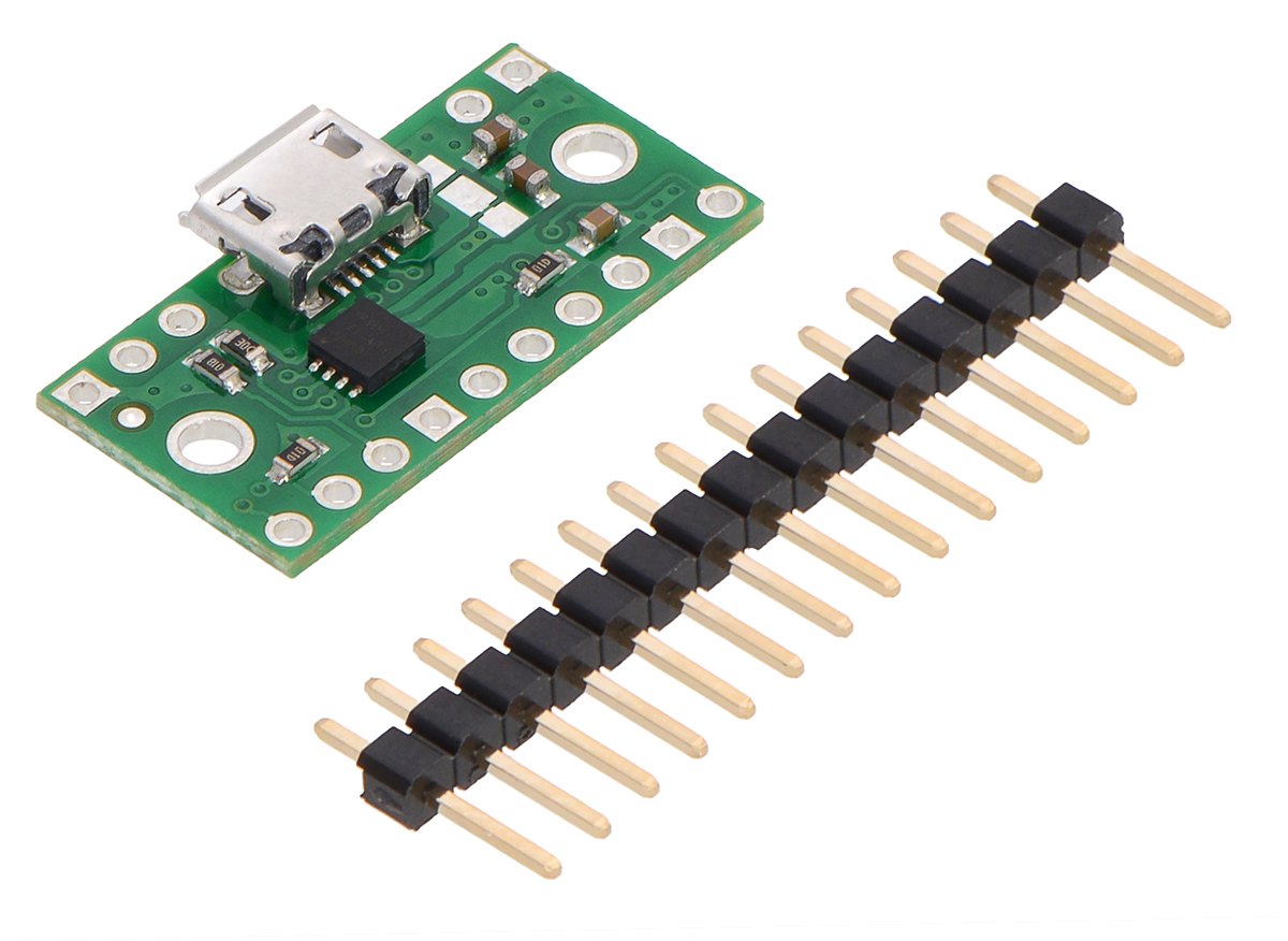
Included hardware
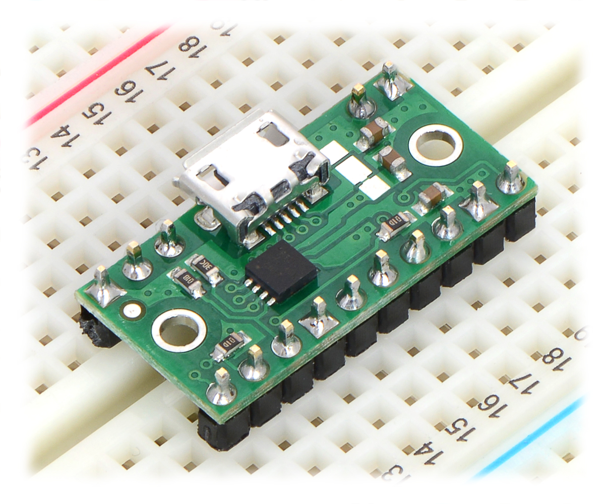
The included 1×15 strip of 0.1″ header pins can be broken into smaller pieces and soldered in to use the board with perfboards, breadboards, or 0.1″ female connectors. The board has two mounting holes that work with #2 and M2 screws (not included).
|
|
Schematic diagram
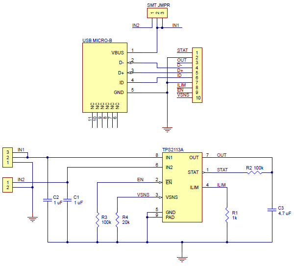 |
This schematic is also available as a downloadable PDF (171k pdf).
People often buy this product together with:
 |
USB Micro-B Connector Breakout Board |
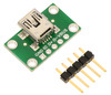 |
USB Mini-B Connector Breakout Board |
 |
FPF1320 Power Multiplexer Carrier with USB Micro-B Connector |
Related products


Home | Forum | Blog | Support | Ordering Information | Wish Lists | Distributors | BIG Order Form | About | Contact
© 2001–2024 Pololu Corporation
