Support » Pololu Wixel User’s Guide » 9. Wixel Apps »
9.b. Wireless Serial App
 |
Wireless PC control of a 3pi robot using a pair of Wixels. |
|---|
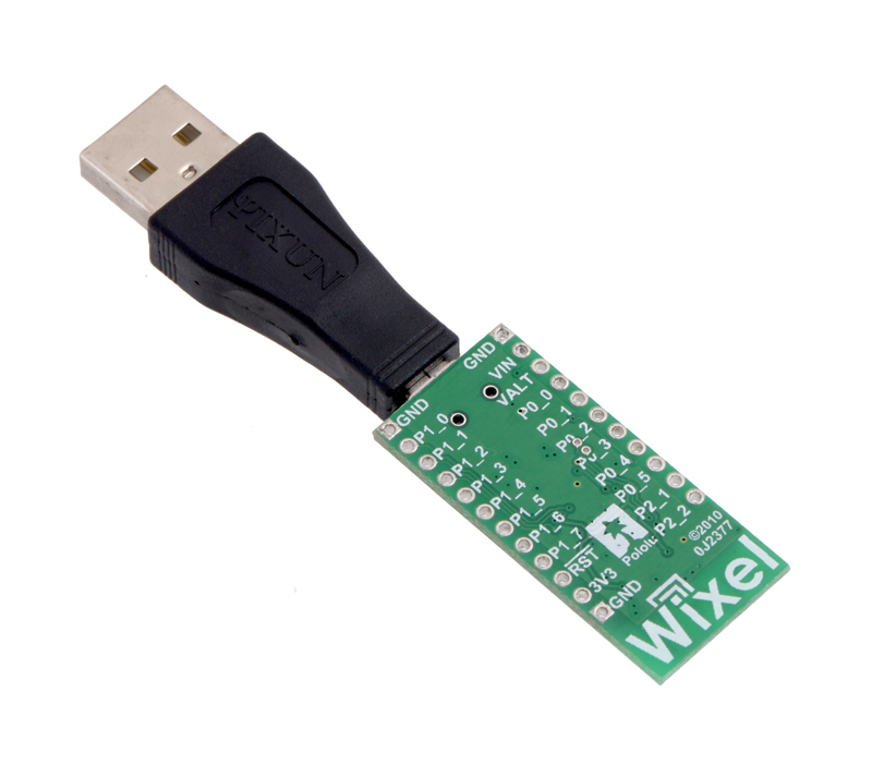 |
Together, the USB Adapter A to Mini-B and a Pololu Wixel wireless module can make a compact USB dongle. |
|---|
Overview
This app allows you to connect two Wixels together to make a wireless, bidirectional, lossless serial link. It uses an RF bit rate of 350 kbps, is capable of carrying up to 10 KB of payload data per second, and can reach a range of approximately 50 feet (under typical conditions indoors). You can also use it to turn one Wixel into a USB-to-TTL serial adapter.
This app can run on multiple pairs of Wixels as long as each pair operates on a different radio channel (the channels should be separated by 2 to avoid interference).
This app is designed for pairs of Wixels; it will not work properly if three or more Wixels are broadcasting on the same radio channel.
Installation Instructions
Download the Wireless Serial App (v1.3) (26k wxl). Open it with the Wixel Configuration Utility, choose your parameters, and then write it to two Wixels. See Section 4 for more information on how this is done.
Default Pinout
| Pin | Function | |
|---|---|---|
| P1_0 | DTR | general-purpose output pin |
| P1_1 | RTS | general-purpose output pin |
| P1_2 | DSR | general-purpose input pin |
| P1_3 | CD | general-purpose input pin |
| P1_5 | PA_PD | radio transmit debug output |
| P1_6 | TX | transmits serial data (0–3.3 V) |
| P1_7 | RX | receives serial data (0–3.3 V, not 5 V tolerant) |
| P0_0 | Arduino DTR | for wireless Arduino programming when used with the Wixel shield |
Description
This device appears to the USB host as a Virtual COM Port (with USB product ID 0x2200). If you are using Windows, you should see an entry labeled “Wixel” in your Device Manager in the “Ports (COM & LPT)” category while the app is running.
There are three basic serial modes that can be selected:
- USB-to-Radio: Serial bytes from the USB virtual COM port get sent to the radio and vice versa.
- UART-to-Radio: Serial bytes from the UART’s RX line get sent to the radio and bytes from the radio get sent to the UART’s TX line.
- USB-to-UART: Just like a normal USB-to-TTL serial adapter, bytes from the virtual COM port get sent on the UART’s TX line and bytes from the UART’s RX line get sent to the virtual COM port.
You can select which serial mode you want to use by setting the serial_mode parameter to the appropriate number (from the list above) or you can leave the serial mode at 0 (which is the default). If the serial_mode is 0, then the Wixel will automatically choose a serial mode based on how it is being powered as described in the table below, and it will switch between the different serial modes on the fly.
| Power Source | Serial Mode |
|---|---|
| USB only | USB-to-Radio |
| VIN only | UART-to-Radio |
| USB and VIN | USB-to-UART |
The RX pin has an internal 20 kΩ pull-up resistor.
The PA_PD pin (P1_5) is a debugging output that goes low while the Wixel is transmitting a packet on the radio.
The serial data format used by this app is 8 data bits, one stop bit, with no parity, which is often expressed 8-N-1. The data is non-inverted, so 0 V represents 0 and 3.3 V represents 1.
Indicator LEDs
The green LED behaves as described in Section 1.a, and also flickers when there is data transferred over USB.
The yellow LED represents the state of the radio. If the Wixel is in a serial mode where the radio is not used, the yellow LED will be off. Otherwise, the yellow LED turns on and off slowly until radio communication is established for the first time, after which it blinks briefly once per second and flickers whenever data is sent or received via the radio.
The red LED indicates errors. The red LED will flash briefly if a byte is received on the UART’s RX line that had to be discarded because the receive buffers were full. The red LED will turn on when a framing error occurs on the RX line and will stay on until the RX line goes high.
Control Signals
In addition to relaying bidirectional serial data, this app also relays the values of four control signals: DTR, RTS, DSR, and CD. The names of these control signals come from the RS-232 protocol, but in this app they do not actually have the same role as they have in that protocol: they are general purpose digital control signals that can carry any kind of data that you want them to, as long as that data changes slowly (on the order of 5 Hz or slower) and is limited to two bits in each direction.
In USB-to-Radio mode, the DTR and RTS signals from USB are transmitted wirelessly to the other Wixel, while the control signals wirelessly received from the other Wixel are relayed to USB as DSR and CD.
In UART-to-Radio mode, the DSR and CD signals from the digital input pins are transmitted wirelessly to the other Wixel, while the control signals wirelessly received from the other Wixel are relayed to the DTR and RTS output pins.
In USB-to-UART mode, the DTR and RTS signals from USB are relayed to the corresponding output pins, while the values of the DSR and CD input pins are relayed to USB.
If two Wixels are communicating wirelessly with each other and both are in UART-to-Radio mode or both are in USB-to-Radio mode, then the correspondence between the control lines is as follows: DSR on one Wixel corresponds to DTR on the other Wixel, while RTS on one Wixel corresponds to CD on the other Wixel.
The default configuration of this app (as shown in the table above) gives the Wixel two inverted output pins (DTR and RTS), and two inverted input pins (DSR and CD). These pins are inverted, which means that a logical value of 0 corresponds to high voltage (usually 3.3 V), while a logical value of 1 corresponds to 0 V (GND).
By changing the configuration parameters (see below), you can disable these signals, reassign them to different I/O lines, or add non-inverted inputs and outputs.
Any pin configured as an input will have an internal 20 kΩ pull-up resistor unless it is assigned to P1_0 or P1_1, which do not have pull-up or pull-down resistors.
You do not have to connect anything to the control signal pins in order to send and receive serial data. These pins are optional.
General Parameters
- serial_mode: Selects the serial mode (1–3, see list above) or auto-detect serial mode (0). The default is 0.
- baud_rate: The baud rate to use for the UART, in bits per second. The default is 9600. We recommend not exceeding 115200. This parameter has no effect on serial communication over the virtual COM port (USB).
- radio_channel: The channel number is from 0 to 255 and determines which frequency to broadcast on. The default is 128. Wixels must be on the same channel to communicate with each other. To avoid interference, Wixels that aren’t supposed to talk to each other should be at least 2 channels away from each other. For example, you could have one pair of Wixels on channel 128 and another pair on 130.
- framing_error_ms: The approximate number of milliseconds to disable the UART’s receiver for after encountering a framing error on the RX line. Valid values are 0–250. The default is 0, which means that the UART’s receiver will not get disabled after a framing error.
Pin Assignment Parameters
The following parameters can be used to reassign the control signals to different pins on the Wixel. The value of each parameter must be the number of an unused pin on the Wixel. The number can be computed by multiplying the first digit in the pin name by 10 and adding it to the second digit in the pin name. For example, if you wanted to assign the DSR pin to P1_2, you would set nDSR_pin to 12. To disable a signal (assign it to no pin), set the corresponding parameter to -1.
- nDTR_pin: The pin assignment for the inverted DTR output. The default is 10 (P1_0).
- nRTS_pin: The pin assignment for the inverted RTS output. The default is 11 (P1_1).
- nDSR_pin: The pin assignment for the inverted DSR input. The default is 12 (P1_2).
- nCD_pin: The pin assignment for the inverted CD input. The default is 13 (P1_3).
- DTR_pin: The pin assignment for the non-inverted DTR output. The default is -1 (disabled).
- RTS_pin: The pin assignment for the non-inverted RTS output. The default is -1 (disabled).
- DSR_pin: The pin assignment for the non-inverted DSR input. The default is -1 (disabled).
- CD_pin: The pin assignment for the non-inverted CD input. The default is -1 (disabled).
- arduino_DTR_pin: The pin assignment for an output for wireless Arduino programming when used with the Wixel shield. The default is 0 (P0_0).
You should not simultaneously enable the non-inverted and inverted input for the same signal. Specifically, either nCD_pin or CD_pin should be -1 and either nDSR_pin or DSR_pin should be -1.
Example Uses
- This application can be used to make a wireless serial link between two microcontrollers, with no USB involved (except for initially configuring the Wixels). To do this, use the UART-to-Radio mode on both Wixels.
- This application can be used to make a wireless serial link between a computer and a microcontroller. Use USB-to-Radio mode on the Wixel that is connected to the computer and use UART-to-Radio mode on the Wixel that is connected to the microcontroller. If you are powering both Wixels in the usual way, you should be able to use auto-detect serial mode (serial_mode = 0).
- If you are doing option 2 above and using the the auto-detect serial mode (serial_mode = 0), then you have the option to (at any time) plug a USB cable directly into the Wixel that is connected to your microcontroller to establish a more direct (wired) serial connection with the microcontroller. (You would, of course, have to tell your computer to switch to the other COM port when you do this.)
Caveats
Data will be lost if the Wixel receives bytes on the RX line faster than the radio can convey them to the other Wixel. If you have trouble, try reducing the amount of data sent to the RX line by lowering the baud rate or adding delays to your microcontroller’s code.
Caution: The Wixel’s I/O lines are not 5V tolerant. You must use level-shifters, diodes, or voltage dividers to connect the Wixel to outputs from 5V systems. Also, avoid drawing more current from an I/O line than it can provide (see the discussion of P1_0 and P1_1 in Section 1.a). Avoid connecting multiple output pins together.
The Wixel does not support the RS-232 voltage levels typically used by DB9 serial ports. The Wixel’s I/O lines, including the RX and TX lines, operate on voltages between 0 and 3.3 V. To connect the Wixel to an RS-232 serial signal, you will need additional level-shifting and inverting hardware like the Pololu 23201a serial adapter (RS-232 serial is inverted; the Wixel’s serial interface expects non-inverted serial).
Versions
- Wireless Serial App v1.3 (26k wxl), released 2011-06-20: Added the framing_error_ms parameter and the corresponding feature for disabling the UART’s receiver after a framing error. Changed the behavior of the red and yellow LEDs; in previous versions the red LED was off and the yellow LED simply indicated the presence of VIN power.
- Wireless Serial App v1.2 (24k wxl), released 2011-04-06: Added support for control signals. As a result, the radio protocol used is NOT compatible with earlier versions. Also fixed a glitch on the TX line that occurred upon power-up or reset. Added blinking behavior to the green LED to indicate USB data transfer.
- Wireless Serial App v1.1 (18k wxl), released 2011-03-23: Improved the radio protocol to fix a problem in v1.0 where if one Wixel resets but the other Wixel does not, then (depending on the state of the other Wixel) there is a 50% probability that the next radio packet sent in either direction will be ignored by the receiver.
- Wireless Serial App v1.0 (18k wxl), released 2011-03-22: Initial release.
Versions Configured for the Wixel Shield for Arduino
These are special versions of the app that have the same code as the corresponding standard versions, but have different settings so that they will work well with the Wixel Shield for Arduino. The default baud_rate was changed to 115200, which is the baud rate used by the Arduino Uno’s bootloader. All the pin assignment parameters were set to -1 (disabled) except arduino_DTR_pin, which was left at 0 (P0_0). The framing_error_ms parameter was set to 5. The only parameters of these apps that can be modified by the user are the radio_channel parameter and baud_rate parameter. For more information about configuring this version, please see the Section 2.c of the Wixel Shield User’s Guide.


Home | Forum | Blog | Support | Ordering Information | Lists | Distributors | BIG Order Form | About | Contact
© 2001–2026 Pololu Corporation
