Support » Pololu Wixel User’s Guide » 1. Overview »
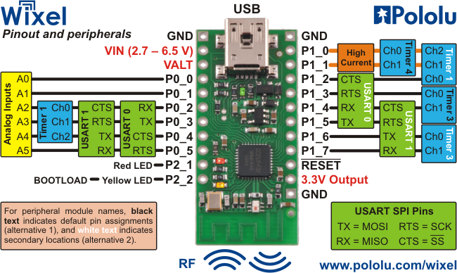
1.a. Module Pinout and Components
 |
The Wixel can connect to a computer’s USB port via a USB A to Mini-B cable or a USB A to Mini-B adapter (not included). The USB connection is used to configure the Wixel and also to transmit and receive data. The USB connection can also provide power to the Wixel.
On the side of the board opposite the USB connector, the Wixel has a 2.4 GHz PCB trace antenna. This antenna, along with the other RF circuitry, forms a radio that allows the Wixel to send and receive data packets in the 2.4 GHz band. The Wixel is based on the CC2511F32 microcontroller from Texas Instruments, which makes it compatible with the CC2500 transceiver, the CC2510Fx family, and the CC2511Fx family of chips from Texas Instruments. The Wixel’s radio is not compatible with Wi-Fi, Zigbee, or Bluetooth. The antenna is a “meandered Inverted F” design that is described in Texas Instrument’s application note AN043.
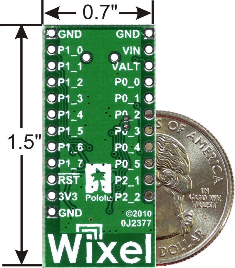 |
Wixel programmable USB wireless module, bottom view with US quarter for size reference. |
|---|
The three GND pins are all connected and are at 0 V by definition. When connecting the Wixel to other electronic systems, you should make sure that the Wixel’s GND is connected to the other system’s GND unless you are doing something very advanced.
The Wixel can be powered from VIN pin. Simply connect a 2.7–6.5 V power source between VIN and GND, with the positive terminal going to VIN. It is OK to connect VIN and USB at the same time. See Section 5.a for more information about powering your Wixels.
The VALT pin is connected to three things: the 5V USB bus power from the USB port (through a diode), VIN (through a diode), and to the input of the Wixel’s on-board 3.3 V regulator. The connection to 5V is switched off when a power supply is connected to VIN. Most people will not need to use the VALT pin: see Section 5.a for example uses.
The pin labeled 3V3 on the board (3.3V Output in the diagram above) is connected to the output of the Wixel’s 3.3V regulator. This power source can be used to power other low-current peripherals in your system. With an input voltage of 5 V (either from USB, VIN, or VALT), this output can provide up to 150 mA of current. At higher input voltages, this output can provide up to 100 mA.
The pin labeled RST on the board (RESET in the diagram above) is the reset line of the microcontroller. This pin can be driven low to perform a hard reset of the Wixel’s microcontroller. This should not be necessary for typical users, but it can be useful while you are developing a Wixel application (see Section 5.c). This pin is internally pulled high to 3.3 V, so it is okay to leave it unconnected. If you do wire something to this pin, the CC2511F32 datasheet recommends adding an external RC filter with values of 1 nF and 2.7 kΩ close to the pin in order to avoid unintended reset of the microcontroller.
The Wixel has 15 free I/O lines whose behavior depends on the application that is loaded onto the Wixel. Specifically, these are all of the pins on Port 0 (P0_0 through P0_5), all of the pins on Port 1 (P1_0 through P1_7), and P2_1. The P2_1 pin is tied to the red LED but the other 14 free I/O lines are only connected to the microcontroller. The P2_2 line is also accessible, but it is tied to the yellow LED and is used to get the Wixel into bootloader mode (see Section 5.c).
The amount of current that can be supplied by the CC2511F32’s I/O pins is not well-documented by the manufacturer. According to this forum post by a TI Employee, regular I/O pins are designed to be able to source 4 mA while P1_0 and P1_1 are designed for 20 mA.
Caution: The Wixel’s I/O lines are not 5V tolerant. You must use level-shifters, diodes, or voltage dividers to connect the Wixel to outputs from 5V systems. Our bidirectional logic level shifter works well for this.
The CC2511F32 has several peripherals that are available to be used in Wixel applications:
- 2 USARTs which can perform asynchronous serial or SPI communication
- 3 timers that are capable of PWM output as shown above, plus 1 more internal timer
- 6 analog input-capable pins, connected to a 7–12 bit ADC
Different Wixel applications may use different sets of these peripherals. Consult the application documentation for details on the behavior of the I/O lines.
The pinout and peripheral diagram at the top of this section is also available as a printable pdf (145k pdf).
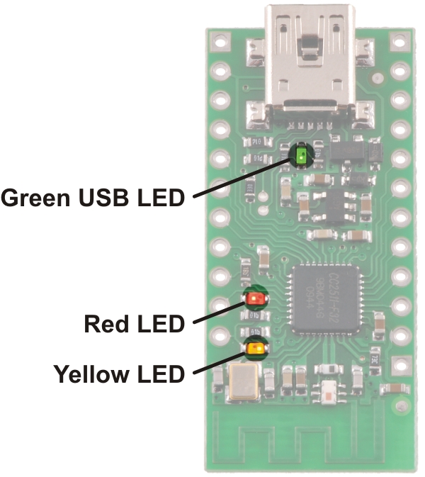 |
Wixel indicator LEDs. |
|---|
The Wixel has three indicator LEDs:
Green USB LED
The green LED is powered from USB, so it can only be turned on when USB cable is connected and supplying power to the Wixel.
While the Wixel is in bootloader mode (i.e. the app is stopped), this LED is used to indicate the USB status of the device. When the Wixel USB Bootloader connects to USB, the green LED starts blinking slowly. The blinking continues until the bootloader receives a particular message from the computer indicating that the Wixel USB Bootloader drivers are installed correctly (see Section 3.a for driver installation instructions). After the bootloader gets this message, the green LED will do a double-blinking pattern. The green LED also turns off during USB Suspend Mode, which happens when the computer goes to sleep or shuts down the USB port for any other reason.
While the Wixel is running its app, the behavior of the LED depends on the app. The standard apps provided by Pololu all behave as follows: When the app connects to USB, the green LED starts blinking slowly. The blinking continues until the app receives a particular message from the computer indicating that the app’s drivers are installed correctly. After the app gets this message, the green LED turns solidly on. The green LED also turns off during USB Suspend Mode, which happens when the computer goes to sleep or shuts down the USB port for any other reason.
Red LED
While the Wixel is in bootloader mode (i.e. the app is stopped), this LED indicates whether there is an application on the Wixel. If there is no application, the red LED will be on. Otherwise, it will be off. By default, the Wixel does not have an application on it, so this LED will be on the first time you power your Wixel.
The P2_1 pin is connected to the red LED, so this line will go high when the red LED is on and otherwise be pulled low.
While the Wixel is running its app, the behavior of this LED depends on the app. See the documentation of your particular app for more details.
Yellow LED
While the Wixel is in bootloader mode (i.e. the app is stopped), this LED turns solidly on and flickers whenever the bootloader receives a command from Wixel software on the computer. The Wixel Configuration Utility queries the state of the bootloader once per second, so if the Wixel Configuration Utility is open then the LED will flicker once per second. While the Wixel is being programmed, the yellow LED will constantly flicker.
The P2_2 pin is connected to the yellow LED, so this line will go high when the yellow LED is on and otherwise be pulled low.
While the Wixel is running its app, the behavior of this LED depends on the app. See the documentation of your particular app for more details.


Home | Forum | Blog | Support | Ordering Information | Wish Lists | Distributors | BIG Order Form | About | Contact
© 2001–2024 Pololu Corporation
