Support » Pololu Jrk USB Motor Controller User’s Guide » 3. Configuring the Motor Controller »
3.b. Input Options
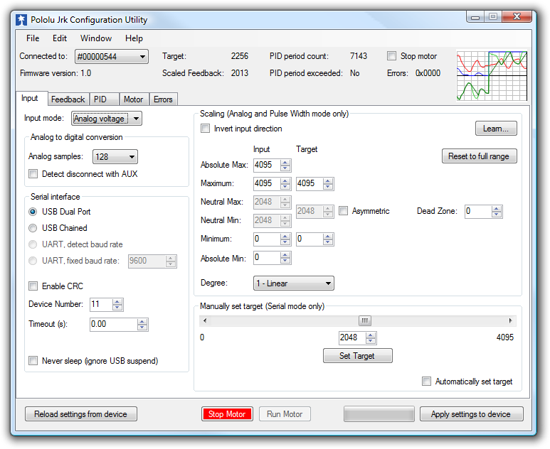 |
The Input tab of the Jrk Configuration Utility |
|---|
The Input tab of the jrk configuration utility contains settings for how the feedback system (consisting of the jrk, a motor and a feedback sensor) is externally controlled and monitored. Most importantly, there are three Input modes:
- Serial indicates that the jrk gets its target setting over a serial interface, either a virtual COM port or the TTL-level serial port of the jrk, as explained in detail in Section 4.
- Analog voltage is used when an analog voltage source, such as a potentiometer, connected to the RX line is used to set the target. A signal level of 0 V on this line corresponds to an input value of 0, and signal level of 5 V correponds to an input value of 4092.
- Pulse width is used when the system is to be controlled by the width of digital pulses, such as those output by a radio-control (RC) receiver, measured on the RX line. In this input mode, the input value is the width of the most recent pulse, in units of 2/3 μs. For example, a pulse width of 1500 μs corresponds to an input value of 2250. This input interface accepts pulses from 400 to 2600 μs at a frequency between 10 and 150 Hz. The jrk will only update the input value if it has received four valid pulses in a row, and it will generate the Input invalid error if it goes more than 120 ms without updating the input value. The voltage of the high pulses must be between 2 and 5 V.
Version 1.3 of the firmware for the Jrk 21v3 and the Jrk 12v12 contains a bug fix that improves the reliability of the Pulse width input. The update is recommended for devices with an earlier firmware version number, including all devices shipped before August 25, 2009. See Section 3.h for upgrade information.
Input scaling
The scaling options in this tab determine how the raw input values map to target values, which determine the output of the system. The parameters Maximum and Minimum should be set to the maximum and minimum possible values of the input device; these will be scaled to the target values specified in the right column. For input devices with a clearly defined neutral position, such as joysticks, parameters Neutral Max and Neutral Min are provided. Any input between Neutral Max and Neutral Min will be scaled to the neutral value specified in the right column. Setting the two neutral values to be different allows for a “dead zone”, which is especially desirable in speed control mode. If the input leaves the range specified by the Absolute Max and Absolute Min parameters, an Input disconnect error will occur. For convenience, the Invert input direction option is provided. Select this option to switch the positive and negative input directions.
By default, the scaling is linear, but you can change the Degree parameter to use a higher-degree polynomial function, which gives you better control near the neutral point.
Clicking the button labeled “Learn…” allows scaling values to be determined automatically: with the motor off, the program will request that the input be set to its minimum, maximum, and neutral positions, and the resulting values will be recorded. After learning, if the neutral position is not important for your system, you may uncheck “Asymmetric” to automatically center the neutral values between minimum and maximum.
Input analog to digital conversion
In analog mode, the analog to digital conversion panel lets you specify the number of analog samples to average together each PID cycle, which determines the precision and speed of the analog to digitial conversions. The indicator labeled “PID period exceeded” at the top of the window is provided as a warning for when the analog sampling takes more time than the specified PID period.
Selecting the Detect disconnect with AUX option activates an extra feature that allows the jrk to detect if the RX pin becomes disconnected from the analog voltage input device or shorted to 5 V. This option is intended for use in analog voltage input mode with a potentiometer connected between AUX and ground. When the option is selected, the jrk will periodically drive the AUX pin low, verifying that this results in a 0 V signal at RX. If the line does not respond as expected, the Input disconnect error will occur.
Serial interface
This panel allows the serial ports of the jrk to be configured, including specifying a fixed baud rate and enabling or disabling a CRC byte for all commands. The Device Number setting is useful when using the jrk with other devices in a daisy-chained configuration, and the Timeout specifies the duration before which a Serial timeout error will occur (a Timeout of 0.00 disables the serial timeout feature).
For more details on the serial interface, especially for selecting the appropriate mode for your system, see Section 4.a.
Manually set target (serial mode only)
This section is provided for debugging and testing systems without using an input device. The target may be specified directly with the scrollbar or numerical input.


Home | Forum | Blog | Support | Ordering Information | Lists | Distributors | BIG Order Form | About | Contact
© 2001–2026 Pololu Corporation
